ÁKOS KUN
Tesla Converter
Motto:
„A day when science begins to investigate non-physical phenomena, it will make more progress in a decade
than in the centuries before that.”
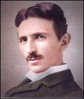
Nikola Tesla

Are we preserving or destroying
our planet?
Tesla converter
(Functional description)
Update: 1 October 2025
Almost everyone has heard of the Tesla converter, but few believe it existed. And official science simply ignores it. According to our scientists, the existence of the Tesla converter is nothing more than a myth. Amateur researchers, lone inventors, have tried to reconstruct it, but without success. The way it worked was unknown, so they did not know how to start reviving it. Instead, they created various perpetual motion devices (perpetual motion machines), which are rather inefficient. Moreover, they contain moving parts and therefore require maintenance. They are also heavy, difficult to move and expensive to produce.
However, there is a great need for a high-efficiency, low-cost, maintenance-free device for generating energy from energy. The use of waste-to-energy could eliminate pollution. There would be no need for air-polluting power stations, and cars would be powered by zero-emission electric motors rather than smoky explosive engines (already in place, but powered by expensive batteries charged by power station electricity). The world's oceans would no longer be polluted by millions of litres of oil from oil tankers that have caught fire and sunk.
The Tesla converter is the most perfect of the currently known compact design surplus energy generation systems. In this device, the excitation is done by the ether, so no external intervention is needed to make it work. Its electronic design means that it can be scaled up or down to any size, and its production is simple and cheap. Since it does not require any external excitation by us, its efficiency is theoretically infinite. Of course, this is limited by feasibility, since above a certain power it would require a transformer of a size that could only be moved by crane, and a wire winding so thick that it could not be bent. But the Tesla converter is not intended to replace a power plant. It is ideally suited for local power supply. It eliminates the need to interconnect consumers, and may even mean that in the future some rooms in homes will not be connected to the electricity grid.
 This is
made possible by the high specific power of the Tesla converter. For example, a
small panel the size of a palm, which can fit in a corner of a device, can
power a communications device. It is therefore possible that in the future
manufacturers will incorporate this inexpensive power source into their
products, thus eliminating the need for a mains connection and making all
electrical appliances self-powered. The
Tesla converters installed in electronic appliances and computers will
no longer produce 230 (110) volts, but will transform their output voltage to
the voltage required by the load circuits (3V, 5V, 12V). In this case, only a simple voltage stabilizer needs to be
connected to the output of the converter.
This is
made possible by the high specific power of the Tesla converter. For example, a
small panel the size of a palm, which can fit in a corner of a device, can
power a communications device. It is therefore possible that in the future
manufacturers will incorporate this inexpensive power source into their
products, thus eliminating the need for a mains connection and making all
electrical appliances self-powered. The
Tesla converters installed in electronic appliances and computers will
no longer produce 230 (110) volts, but will transform their output voltage to
the voltage required by the load circuits (3V, 5V, 12V). In this case, only a simple voltage stabilizer needs to be
connected to the output of the converter.
For radiator-type electric heaters (oil radiators), the box that supplies the power will probably be mounted on the side, while for electric heaters, the high-power converter is expected to be mounted on the bottom. It is also possible that we will be able to produce miniature converters in integrated circuit design that can be installed in clocks. This will not only make portable electronic devices much cheaper to run, but will also get rid of the environmental pollution caused by the billions of spent batteries and accumulators that are currently being thrown away. At the same time, the grotesque situation where batteries often cost more than the device they are put into will be eliminated. This is mainly due to the fact that dry cell manufacturers, taking advantage of consumer dependency, have in recent years raised the price of their products to the stars.
The need to harness and harness universal energy is therefore urgent in all areas. The task is not so great, because the Tesla converter has been proven to exist.[1] With today's modern components it could be built cheaply and in a few weeks. Before that, Nikola Tesla's patent specifications must be studied, with particular reference to the converter. This should not be too difficult, as Péter Varsányi has collected all of Tesla's patents and even had most of them translated into Hungarian (e-mail: info@varsanyipeter.hu Tel: +36-20-942-7232.) His collection, which has been created with enormous effort and at great cost, can be found at http://www.Tesla.hu The scanned pages are saved in GIF format. Some of the text has been digitised using OCR (character recognition) software, and even the most important patent specifications have been translated into Hungarian. Here you can find all the books, articles and invention descriptions of the two inventors. The material is still being expanded, with the addition of previously unknown writings discovered later.) With this information and the circuit diagram, you can start building the device.
Let us start with the basics. This is necessary because the working mechanism of the Tesla converter is unknown. The reason for this is not secrecy but lack of theoretical knowledge and technical terms. Tesla himself, and later Moray, did not know the exact operating mechanism of his device. Henry Moray, who revived and improved the Tesla converter, only told his assistant about his device: 'Size: 61 × 25 × 15 cm. As for its internal construction, it has 12 vacuum tubes, three of which are of the 70-L-7 type." From this scant information, it can be concluded that the Tesla converter consisted of 12 stages connected in a cascade, with the vacuum tube acting as a diode. The 3 electron tubes were probably low threshold voltage and were installed in the first three stages. After that, the output voltage was so high that ordinary electron tube diodes were sufficient.
So, first, build 12 conventional parallel LC circuits and connect them in series. (Use primary and secondary windings of increasingly high power transformers as inductors.) Switch an ordinary sine wave signal to the first stage using a signal generator. Connect a voltmeter or oscilloscope to the secondary winding of the last stage. You will find that the amplitude of the output signal, i.e. its power, is not even equal to the input signal. This is due to the thermal movement in the interconnecting wires and transformer windings, and the inductive energy is almost dissipated in each stage due to Lenz's law. Now let us set the frequency of the sine wave to the resonant frequency of the resonant circuits. We then find that the output signal is almost as high as the input signal. This small loss is due to the fact that the mechanical vibration of the atoms in the metal wires causes a significant amount of free electrons to be stripped from their outermost electron shells. RC, LC, RLC circuits tuned to resonance are used in communications technology, microwave technology (mobile phones, satellites). They are used in modulator coils, low-pass and high-pass filters and other resonators.
These are all useful circuits, without them there would be no electronic communication in our world, and we would even have to do without electronic musical instruments (e.g. synthesizers). However, these conventional parallel resonant circuits are not suitable for generating additional energy. In fact, for the reasons just mentioned, they have to suffer some losses during operation and therefore need power to make up for the losses that occur during operation. At present, these circuits are used for both signal transmission and reception (radio transmitters, TV transmitters, mobile phone stations). In this application, the main problem is not that no excess energy is generated, because that is not the aim. The bigger problem is that this type of excitation limits the speed at which electromagnetic waves can propagate. Since electrons create the induced voltage, the speed of the emitted signal does not exceed the speed of the electron. As we know, this is not faster than the speed of light, i.e. 300,000 km/s rounded up.
Here on Earth, this propagation speed is satisfactory, but in space it is a barrier to interactive (no-delay) communication.[2] And in the cosmos, this system is completely useless, because even the nearest star to us would have a delay of 4 years before it would send a signal to us. That is why extraterrestrials do not use this obsolete method of communication. They use etheric particles, which flow at a speed 12 orders of magnitude faster than the electron. This method of signal transmission is not completely unknown to us either, because Tesla invented it 120 years ago, but no one bothered to use it. Instead, our civilisation introduced the Marconi system of communication based on transverse waves. But we would have been better off with Tesla's longitudinal-wave transmission method.
The ingenious communication system he invented was ready for practical application at the end of the 19th century. He designed not only the etheric receiver, but also the transmitter, and in a portable version. His 1899 description of the invention and the accompanying wiring diagrams are proof of this. But he considered the idea of a mobile phone, born over a hundred years ago, so futuristic that he did not even apply for a patent. Let's not forget that Popov was only experimenting with a scimitar at the end of the 19th century, and Marconi got as far as sending a Morse code signal across the Atlantic in 1901. The radio he developed became capable of transmitting speech in 1921. So Tesla had no hope of obtaining a patent for a radio telephone a quarter of a century earlier, before scientists even knew what a radio was.
Few people are aware of this fact in the history of technology. During the decades of communist dictatorship, children were taught in school that the inventor of the radio was the Russian Popov. In Western schools, the name of the Italian Marconi was drummed into children, even though Tesla, who lived in America, was way ahead of them all. After three decades of litigation, this was recognised by the US Supreme Court. In an unappealable decision, Tesla was awarded the right to invent the radio, but none of the people involved were alive at the time. And the world couldn't care less who invented the radio. People were happy that it had been born, and listened to the rapidly multiplying number of transmitters.
In the communications system we use, we produce a high-frequency carrier wave and superimpose the signal to be transmitted on it. This is called modulation. In the receiver, the demodulator separates the useful signal from the carrier wave and amplifies it to make it audible and watchable. This also sets the aether in motion, but we cannot use it because our receivers can only detect harmonic, transverse signals. We do not even pay attention to this side phenomenon because our experts have no idea that they are also transmitting etheric signals. However, extraterrestrials are aware of this phenomenon and even exploit it. This is why civilisations hundreds of light years away are constantly watching our TV programmes. Even civilisations thousands of light-years away have no problem with this, because the poor propagation properties of electromagnetic waves mean that we emit them at least a thousand times more intensely than we would need to detect them in the Milky Way.
The transversal signal decays, becomes smaller and smaller in amplitude after its appearance and then dies out. Therefore, care must be taken to ensure that the signals are continuously generated so that the field strength, and hence the volume in the receiver, does not diminish. Since the intensity of the transverse waves decreases in proportion to the square of the distance, maintaining the carrier waves at the same level also requires a great deal of energy. These effects together mean that a small power plant is needed to power our long- and medium-wave transmitting stations. (We currently drag a few gram-atoms of electrons back and forth in our several-tonne steel colossuses called antennas, with megawatts of energy input.
Backwards, however, this method doesn't work. We cannot intercept their communications because the receiver circuits we use can only detect transverse waves. This is why SETI participants cannot pick up any meaningful signals from space, even though we are almost inundated with magnetic waves from all over the world. We can't even detect the gigantic longitudinal waves of stellar explosions, which radiate almost instantaneously throughout the universe. This is why our radio telescopes can only study what the universe was like millions or billions of years ago. We have no idea what is happening in the universe at the moment.
 Back to
the question of excess energy production by means of transverse waves,
electromagnetic energy cannot be produced. You need another wave.
Fortunately, the situation is not completely hopeless. Indeed, nature produces
a waveform whose strength does not diminish,
but even increases as it progresses.
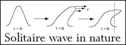
This is the soliton wave[3],
which, unlike a linear wave, travels for kilometres without damping. In
free water, soliton waves are generated at the surface. The most frightening
example of their generation is earthquake-generated tsunamis, which travel
thousands of kilometres in the ocean before breaking on shallow shores and
releasing their destructive energy. On 26 December 2004, an underwater
earthquake of magnitude 9.3 sent a tsunami with a death toll of nearly a
quarter of a million people across the Indian Ocean. Another interesting
manifestation is a torrential tidal surge,
when a wave generated by a tide rises up a river bed. The secret of their
smooth progress is the ether. The soliton wave rises slowly and its
height drops suddenly. As the wave height drops precipitously, ether particles
flow into the resulting space. The etheric particles, which quickly enter the
trough, push the water wave through inertia, causing it to move forward. This
push is so strong that it keeps the wave from dying for a long time. And its
power is colossal. On 9 July 1958, a 500-metre-high swell reached the coast of
Alaska at a speed of 790 km/h.
Back to
the question of excess energy production by means of transverse waves,
electromagnetic energy cannot be produced. You need another wave.
Fortunately, the situation is not completely hopeless. Indeed, nature produces
a waveform whose strength does not diminish,
but even increases as it progresses.
This is the soliton wave[3],
which, unlike a linear wave, travels for kilometres without damping. In
free water, soliton waves are generated at the surface. The most frightening
example of their generation is earthquake-generated tsunamis, which travel
thousands of kilometres in the ocean before breaking on shallow shores and
releasing their destructive energy. On 26 December 2004, an underwater
earthquake of magnitude 9.3 sent a tsunami with a death toll of nearly a
quarter of a million people across the Indian Ocean. Another interesting
manifestation is a torrential tidal surge,
when a wave generated by a tide rises up a river bed. The secret of their
smooth progress is the ether. The soliton wave rises slowly and its
height drops suddenly. As the wave height drops precipitously, ether particles
flow into the resulting space. The etheric particles, which quickly enter the
trough, push the water wave through inertia, causing it to move forward. This
push is so strong that it keeps the wave from dying for a long time. And its
power is colossal. On 9 July 1958, a 500-metre-high swell reached the coast of
Alaska at a speed of 790 km/h.
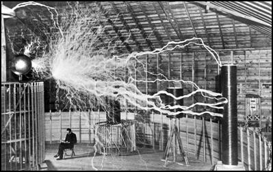
The potential of soliton waves in the electrical industry was recognised by Nikola Tesla. He first studied its travel in gases. Very soon he realised that the excess energy generated by longitudinal waves is accumulated (added up) as they radiate. Taking advantage of this phenomenon, Tesla used longitudinal waves to create spheres of light, or glowing light in space. He accumulated so much energy in the air that it ionised the air molecules, turning them into plasma. In one of his favourite stunts, he put two metal plates down in the room and the surrounding air soon glowed with a uniform light. He also demonstrated a very high luminosity lamp resembling a gas-discharge fluorescent tube in lectures to the public in New York, London, Paris, Philadelphia and St Louis. (This was in fact an antenna which, when inserted into the tube, irradiated its interior with longitudinal waves.) In his memoirs he wrote of this tube: 'I have made very interesting experiments with vibrating columns of gas. I made some very interesting experiments with oscillating waves. The gas discharge tube was 1 inch in diameter and 1 meter long. I covered both ends and pumped air from it until the discharge started. Later it turned out that it was better to use only one electrode." With this tube, he could also generate energy. He once said that the greatest invention of his life was a tube from which a lot of energy could be extracted.
He told a journalist about this tube: "It's a new kind of tube and the apparatus that goes with it. As early as 1896 I used a tube that worked at 4 million volts. Later on I managed to reach 18 million volts, but then I ran into obstacles that seemed insurmountable. I became convinced that we had to develop a completely different type of tube to overcome these problems. This proved to be a much more difficult task than I had expected, not primarily in making the tube, but in making it work. For years, progress was slow. Then I achieved complete success. I invented a pipe that is difficult to improve. It is ideally simple, does not weaken over time and can be operated at any high potential or voltage. Quite high currents can flow through it and it can be used for energy conversion at any realistic level. It is easy to control and therefore I can expect very big results. Among other things, it will enable us to produce cheap radiative materials in any quantity, and will be much more efficient than converting material by artificial radiation."
His carbon-button lamp was a spherical vacuum tube. The only electrode was a circular flat plate of carbon, and the high-frequency current caused the gas to vibrate continuously inside the tube, glowing and giving off a beautiful light. This phenomenon was made possible by the constant bombardment of the electrode, the thinned gas (plasma) around the electrode vibrated at high speed and frequency. This curious little spherical lamp was also the ancestor of the electron microscope, because the device known as the ion microscope is based on a similar principle.
Tesla also created lossless lighting with these experiments. Longitudinal waves excited the fluorescent layer on the inside of the tube without any heat loss. (Even after 100 years, only 3% of the energy fed into our incandescent lamps is still used as light, while only 10% is used in our fluorescent tubes. The rest is converted into heat, wasted. This phenomenon is particularly unpleasant in film and TV studios, where poorly efficient lamps create a hellish heat. Temperatures of several hundred degrees Celsius will quickly destroy even an incandescent lamp, which burns out with a huge explosion.) Tesla's lamp, on the other hand, which is excited by magnetic pulses, never fails. Since it contains no filaments, there's nothing to go wrong. Even if air gets into it, it doesn't fail, because the light-emitting layer is not excited by electron emission in a vacuum, but by etheric energy particles that ionise the air molecules. It is likely to be the ideal light source of the future. The price will not be high either, as the electronic design of the soliton excitation is no more complex than that of a compact lamp.
 By using
soliton waves extensively, Tesla has also demonstrated motors that were connected
to the grid with only one wire, with the energy propagating through the air
instead of the other wire. Often interesting, unexpected results were achieved.
One day, experimenting in the relatively clear air, he noticed that a fog had
formed in the large laboratory so thick that he could barely see his hands.
Although he did not set out in this direction, he felt that the effect could be
used to irrigate dry places. Another interesting thing that can be gleaned from
his diary is that strange fireballs appeared
during his experiments and moved relatively slowly, usually in a
horizontal direction. These fireballs were already known as ball lightning and
Tesla had heard of them. Did he produce ball lightning? In any case, he
describes it clearly in his diary. He argued that the initial energy might not
be enough to keep the phenomenon alive, but that it would receive constant
energy from the sparks around it, and so it
could exist continuously. This theory was revived decades later by Nobel
laureate Pyotr Kapica, but it has not
been experimentally proven that these glowing spheres do indeed exhibit
the same properties as the spherical lightning observed in nature.
By using
soliton waves extensively, Tesla has also demonstrated motors that were connected
to the grid with only one wire, with the energy propagating through the air
instead of the other wire. Often interesting, unexpected results were achieved.
One day, experimenting in the relatively clear air, he noticed that a fog had
formed in the large laboratory so thick that he could barely see his hands.
Although he did not set out in this direction, he felt that the effect could be
used to irrigate dry places. Another interesting thing that can be gleaned from
his diary is that strange fireballs appeared
during his experiments and moved relatively slowly, usually in a
horizontal direction. These fireballs were already known as ball lightning and
Tesla had heard of them. Did he produce ball lightning? In any case, he
describes it clearly in his diary. He argued that the initial energy might not
be enough to keep the phenomenon alive, but that it would receive constant
energy from the sparks around it, and so it
could exist continuously. This theory was revived decades later by Nobel
laureate Pyotr Kapica, but it has not
been experimentally proven that these glowing spheres do indeed exhibit
the same properties as the spherical lightning observed in nature.
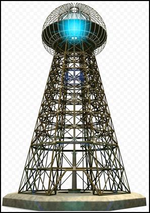
It also soon became clear that soliton waves are most effective at exciting the aether. For this purpose, he built the famous Tesla coil[4], which he used to generate excitation voltages of several million volts. This was the way he wanted to realise his dream of wireless power transmission. Fortunately, it failed because he did not receive funding. If it had been realised, it would have created a strong electro smog in the area that would have destroyed the biosphere. The energy transmitted through the ether induces electricity not only in metal conductors but also in electrolytes (switched-off electric lights have been lit up for miles around Tesla's laboratory in Colorado Springs). Intense magnetic excitation also causes cancerous lesions in animals and plants. The energy should therefore not be transmitted either through the ether or through power lines, because even a high-voltage power line within a radius of 100 metres can cause cancer in living tissue. The energy must be generated on site, at the user, and transported by the shortest possible cable to the load, i.e. the power-consuming device.
As you can see, all of Tesla's inventions are based on the use of soliton waves, also known as translational waves. A soliton is a pulse with a slope greater than its rise time. Its regular waveform is not known but is already in use. In the fibre optic cables that make up optical fibres, soliton signal transmission ensures lossless transcontinental communication. It is this specific light wave that allows the Internet to cover the entire globe. After the failure of wireless power transmission, soliton excitation was reintroduced in the early 1930s. In developing the converter that bears his name, he soon realised that he could not do without soliton waves. The LC resonant circuits cascaded in a cascade, which were found to be suitable for energy multiplication, could not produce excess energy even when tuned to resonant frequencies. To do this, energy must be accumulated in the metallic conductors. In metallic conductors, energy is created by free electrons. So they have to be multiplied.
The soliton wave is also suitable for this, only the signal shape of the excitation current has to be modified. The sine waveform that allows harmonic oscillation must be replaced by a soliton-shaped excitation signal. Then, in the slow-ramp-up phase, conventional excitation takes place in the metallic conductor, in this case the inductance. However, after reaching its maximum value, the voltage is suddenly interrupted. The free electrons are then ordered back to the outermost electron shell of the metal atoms. The universe, however, cannot tolerate the vacuum and tries to fill it as soon as possible, so the free electrons are replaced by ether particles (ether ions) that penetrate the metallic conductor. They collide with the metallic atoms at a speed of up to 12 orders of magnitude greater than the speed of electrons, and separate large amounts of electrons from their outermost electron shells. Then comes another run-up phase of the soliton wave, which further increases the number of free electrons due to its excitation effect. Then the excitation stops again, and now even more free electrons are rearranged. This causes the gap in the metallic conductor to become even larger, allowing even more ether ions to flow in. Thus, cumulation occurs, which, multiplied in each step, results in significant excess energy. This then just needs to be coupled out of the converter. Of course, the multiplication process cannot go on indefinitely because the number of metal atoms in the thin copper wire of the inductance is limited. The next stage, however, contains a larger transformer with a thicker wire, so there is no obstacle to further multiplying the energy obtained.
Tesla and Moray transformed the excess high-voltage current produced by voltage multiplication at the end of the chain to a value that could be connected to ordinary electrical loads. This proportionally increased the load capacity of the converter, which meant that this particular device was capable of delivering currents in excess of 10 amperes in addition to the normal mains voltage. However, by increasing the number of voltage multiplying units, this capacity could be further increased. The circuit according to the invention was probably designed for this capacity because this power was already capable of meeting the needs of the time. The inventors also placed great emphasis on small size and portability, as they often had to demonstrate at public demonstrations that the box in which the device was housed could not accommodate a battery large enough to power an iron and high-intensity incandescent lamps connected to the output for hundreds of hours of observation. Ease of transport was also necessary because the device has been taken on more than one occasion in different vehicles to prove, in a remote desert or in the middle of the ocean, that the converter does not draw its energy from the power lines of inhabited settlements or from the signal of nearby radio transmitters, but actually generates it using the ether.
In devising the principle of energy multiplication, Tesla also chose parallel LC circuits because he had already realised during the design of the Tesla coil that the higher the voltage, the greater the soliton effect. By cascading the parallel LC circuits, it is possible to transform the voltage of each stage upwards. The primary winding of the twelfth stage probably already had a voltage as high as that measured in the series transformer (mill winding) of our cathode ray tube television. The Tesla converter is therefore quite dangerous. The breakdown strength of dry air is 21 kV/cm. In a room with humid air, this can be reduced by half. It is therefore strictly forbidden to touch the converter once it has been dismantled from its metal housing and connected. After disconnecting it, wait until the energy in the capacitors has been discharged.
Extra care must also be taken when reconstructing the converter, as even a careless movement can result in a fatal electric shock. (If it is unavoidable to touch a working appliance, put on rubber gloves used by electricians. And attach three catches to the ceiling above the appliance. On two of them, hang a sign above the appliance with the inscription: WARNING: HIGH VOLTAGE! For emphasis, paint a skull and crossbones underneath. From the third hook, hang a high-intensity incandescent lamp of at least 500 W, which, when switched off, is hung on the appliance. Reach in only when the light from the bulb goes out. This may keep you alive.[5]
Developing the Tesla converter was not as easy as we might think today. The implementation of soliton excitation was not easy. At the time of Tesla's work, at the end of the 19th century, there were no diodes, no transistors, and even less a signal generator. Tesla used a spark gap generator to produce soliton waves. (He called this mechanical signal generator a specially designed alternator.) This mechanical signal generator is nothing more than a converted alternating current motor. In this case, the electric machine is not a motor, but a generator. Now, an external motor must be used to drive the single-phase AC motor and the soliton signal must be diverted from it by the carbon brush. The AC generator is not suitable for this purpose, because the current generated in it is not conducted by a commutator but by slip rings. The spark gap, which is very important here, is therefore eliminated. The asynchronous motor is also not suitable because it has no commutator due to the short-circuited rotor. The excitation current flows up the commutator plates and is then suddenly interrupted by the insulating gaps between the commutator plates. The excitation is then stopped. This creates a continuous wave consisting of signals with a slow rise and then a fast decay. This is nothing other than a soliton wave. Tesla didn't know this because at the time there was no name for this generating nonlinear wave.
The imitators also found a simple method to produce soliton waves. They fixed an insulating disk perpendicular to the axis of an electric motor, on which they had previously formed metal lamellae. A carbon brush was pressed against this, which acted like a commutator as the disc rotated. However, it was not mechanically stable. Today, there is no need to struggle with mechanical generators that are unreliable and subject to wear and tear, because transistorised and now integrated amplifier signal generators produce signals of stable frequency and shape. With this in mind, it is easy to revive this device.
Because of the mechanical method of generation, Tesla struggled a lot with the tuning of the converter. He solved the problem of tuning each stage to its resonant frequency by making the iron core of the transformer's primary winding movable in and out, and by inserting a variable-capacitance capacitor between the high-frequency generator and the primary winding. We can use this method effectively to bring the board model to life. By rotating the capacitor and adjusting the amount of insertion of the iron core, we can quickly tune to the resonant frequency. Instead of a rotary capacitor, we can also use a capacitive decadic cabinet, but the coil cannot be replaced by an inductive decadic cabinet, because here we do not need to tune a simple inductance, but a transformer. In the final version of the converter, there is no longer room for a push-in iron core. At the end of the development, precisely sized transformers (operating at resonant frequency) must be used. This can be achieved by reducing or increasing the number of turns of the primary and secondary windings.
In our experiments, we should not forget that we are dealing with high frequency excitation, so we have to use ferrite core transformers. A conventional soft iron plate transformer saturates above 150 Hz. To reduce the risk of breakdown, the output transformer should be modelled on the old cathode ray tube transformer of the old cathode ray tube television sets. This type of design provided a high degree of safety for the excitation of colour television picture tubes up to 45 kV. Tesla set the excitation frequency to between 20 and 30 kHz. This does not mean, of course, that we cannot try higher values. With signal generator excitation, there is no problem. Tesla was not able to do this because he could not spin the AC motor producing the soliton wave at too high a speed. (There are ferrite cores that can be operated up to 1 MHz, but all ferrite core transformers can be excited up to 60 kHz.) With antenna excitation, we will not be able to do this because in this classical version the frequency of the aether noise clearly determines the resonant frequency of each stage.
 The next
step in the reconstruction is therefore soliton excitation. This is not easy
for us either, because there are currently no soliton generators in production.
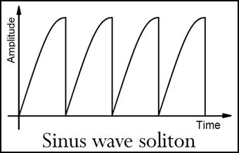
The signal generators on the market, also
known as function generators, function generators or signal generators, produce sine wave, square wave
and sawtooth signals. However, the bisected sine signal is probably suitable
for this purpose. Connect it to the input of the first stage and set its
frequency to the resonant frequency of the LC
circuit tested earlier. We find that
the resonant circuit works, but does not produce excess current. Despite
the soliton excitation, the current in the resonant circuit does not increase, but only circulates. The capacitor is
charged when the signal rises and discharged when it falls. Its energy
is transferred to the inductance. The
magnetic field of the inductance
then collapses and its energy flows in the opposite direction into the capacitor. The coil and the
capacitor alternately act as energy source and energy storage. The result is
oscillation.
The next
step in the reconstruction is therefore soliton excitation. This is not easy
for us either, because there are currently no soliton generators in production.
The signal generators on the market, also
known as function generators, function generators or signal generators, produce sine wave, square wave
and sawtooth signals. However, the bisected sine signal is probably suitable
for this purpose. Connect it to the input of the first stage and set its
frequency to the resonant frequency of the LC
circuit tested earlier. We find that
the resonant circuit works, but does not produce excess current. Despite
the soliton excitation, the current in the resonant circuit does not increase, but only circulates. The capacitor is
charged when the signal rises and discharged when it falls. Its energy
is transferred to the inductance. The
magnetic field of the inductance
then collapses and its energy flows in the opposite direction into the capacitor. The coil and the
capacitor alternately act as energy source and energy storage. The result is
oscillation.
 However,
what we need now is not an oscillator operating at resonant frequency, but an
energy absorber. We can achieve this by preventing oscillation and preventing
magnetic energy from flowing back into the coil. Tesla solved this problem
very simply. He inserted a diode between the coil and the capacitor. Since
current can only flow in one direction through the diode, it cannot flow
backwards. So there is no oscillation. Tesla put this requirement as follows.
In producing this wave, harmonic oscillations must not be allowed, the current
pulses must be unidirectional." Since the current cannot flow backwards,
the next soliton wave will build on the previous one. This increases the
energy in the inductance, in this case the
primary winding of the transformer. Moray called this process "winding". Tesla's
configuration is only apparently similar to conventional transformers, the mechanism of operation being very different. This circuit is nothing more
than a cumulator combined with a transformer. The voltage of the energy waves
collected by the cumulator is transmitted by the transformer by transforming it
up.
However,
what we need now is not an oscillator operating at resonant frequency, but an
energy absorber. We can achieve this by preventing oscillation and preventing
magnetic energy from flowing back into the coil. Tesla solved this problem
very simply. He inserted a diode between the coil and the capacitor. Since
current can only flow in one direction through the diode, it cannot flow
backwards. So there is no oscillation. Tesla put this requirement as follows.
In producing this wave, harmonic oscillations must not be allowed, the current
pulses must be unidirectional." Since the current cannot flow backwards,
the next soliton wave will build on the previous one. This increases the
energy in the inductance, in this case the
primary winding of the transformer. Moray called this process "winding". Tesla's
configuration is only apparently similar to conventional transformers, the mechanism of operation being very different. This circuit is nothing more
than a cumulator combined with a transformer. The voltage of the energy waves
collected by the cumulator is transmitted by the transformer by transforming it
up.
Now there is no obstacle to the production of excess energy. However, it does not go very far. Although soliton waves can generate a lot of power, they can only do so if they have a lot of mass. In circuits with low-mass components, they cannot produce several kilowatts of excess current. The voltage of the electricity produced can be increased to millions of volts, but the current will be small. Tesla's spectacular demonstrations of this power flowing through himself on more than one occasion prove this. The high-frequency, high-voltage current passing through him did him no harm, though sparks did fly from him and he himself swam in the darkness in a ghostly blaze of light. The low current and the skin effect did him no harm. If he touched a 750,000-volt transmission line like that, he'd burn to a cinder. There's electricity in it. Despite the low amperage, the multi-stage converter provided at least 10 kW of additional energy. The diodes were also involved in the power generation.
Since there was no oscilloscope in Tesla's day, the inventor was unaware that the high metal content of cold cathode electron tube diodes had a negative internal resistance. This means that they not only rectify, but also produce excess energy. And not a little of it. We can use this additional energy, but in the age of semiconductors, it is more complicated to achieve. The main problem is that conventional double-layer germanium and silicon diodes do not have negative internal resistance. Tunnel diodes (Esaki diodes and backward or Gunn diodes) do. But these diodes have very low reverse voltages. They could only be used in the first three stages. In the further stages, they would become short-circuited due to the voltage build-up. For these grades, a tunnel diode with a high closing voltage is needed. This can only be achieved by adding a low-doped semiconductor layer to the tunnel diode. This three-layer diode can be used in all stages because it has a low opening voltage and a high closing voltage.
Such a diode is not yet produced anywhere. However, the possibility exists. One of my inventions of forty years ago can presumably satisfy these two requirements. The functional and patent description of my invention, Field Electric Semiconductors, can be found in the Kun Electronic Library. A semiconductor factory would have to manufacture samples and measure them. If their threshold voltage drops to near zero and their load characteristics bend back strongly, we have a winning case. In this case, there is nothing to stop us from reconstructing the Tesla converter with modern components.
Nor do we have to wait for the samples of field-electric semiconductors to arrive. Although pnp-type transistors only rarely exhibit negative internal resistance, the majority of npn-type transistors do. This is most evident in the 2N1613 transistor. npn transistors are very easy to convert to field effect diodes. All that is needed is to short-circuit their base electrode to their collector electrode. You have a bipolar power-generating diode. The only drawback is that its threshold voltage is 0.6 V, so it can only be used in stages where the primary coil voltage is well above this value. In the last stages, high current transistors are needed. Therefore, the load characteristics of high power npn transistors should be measured and the one with the most bias curve should be chosen.
Using semiconductor diodes and a stable signal generator, it may be easy to build a Tesla converter with fewer cascaded stages. No adjustment of the signal generator is needed, because it has no moving parts and requires no maintenance. Of course, a whole signal generator does not have to be built into a series-produced Tesla converter. Only the circuit that produces the split sine wave needs to be mounted on a small panel. This should be designed as a CMOS circuit (p and n type FETs) to minimise the current consumption. If we are designing a miniature signal generator, it would be worthwhile to develop a type where the sine wave is not cut in two, but just pre-decided, like a natural soliton wave. In this way, sine waves similar to those of a rapids would be generated. Such waves can be seen in videos showing surfers.[6] For experimental purposes, a second potentiometer should be fitted in addition to the frequency-control potentiometer to vary the rightward slope of the sine curve. By alternating the two types of signal, it would be possible to decide which excites the Tesla converter more efficiently.
The most suitable battery to power it would be the lithium battery used in notebooks. This long-life battery can power the Tesla converter for up to 10 years. For operational safety, the battery should be connected to the excitation circuit with a soldered connection. The battery holder in portable devices cannot be used here. The spring contacts will corrode over time, resulting in power failure. Some devices, such as computers, will stop working after only a few hundredths of a second of power failure. In the event of a power failure, neither word processing programs nor the operating system will return the opened document, so the whole day's work can be lost. And if you use the Tesla converter in a car, the battery can easily be ripped out of the battery compartment. This can cut off the power to the engine, which can cause a fatal accident.
 A better
solution is to use the voltage fed back from the output to power the signal
generator. The consumption of a few milliamperes can be provided by a small
transformer and a valve transistor stabilised by a Zener diode on its base. The
disadvantage of this solution is that a small inductor is required to revive
the signal generator. This is nothing else than a soliton coil with a high
field magnet rod pushed inside. (Tesla used it to revive his converter.) This
can be automated with a push-button solution. Pressing the start button a few
times charges a buffer capacitor, which, when connected to the signal
generator's supply voltage, can start the circuit. Tesla did not have a signal generator solution because transistors
were not available at the time. He could only generate soliton waves with a commutator motor.
However, the installation of such a motor would have significantly increased
the size of the converter and would have consumed a significant part of the extra
current. He therefore used ether noise for
excitation. However, this method requires a zero threshold voltage
diode, which is unlikely to be produced
from a semiconductor.[7]
A better
solution is to use the voltage fed back from the output to power the signal
generator. The consumption of a few milliamperes can be provided by a small
transformer and a valve transistor stabilised by a Zener diode on its base. The
disadvantage of this solution is that a small inductor is required to revive
the signal generator. This is nothing else than a soliton coil with a high
field magnet rod pushed inside. (Tesla used it to revive his converter.) This
can be automated with a push-button solution. Pressing the start button a few
times charges a buffer capacitor, which, when connected to the signal
generator's supply voltage, can start the circuit. Tesla did not have a signal generator solution because transistors
were not available at the time. He could only generate soliton waves with a commutator motor.
However, the installation of such a motor would have significantly increased
the size of the converter and would have consumed a significant part of the extra
current. He therefore used ether noise for
excitation. However, this method requires a zero threshold voltage
diode, which is unlikely to be produced
from a semiconductor.[7]
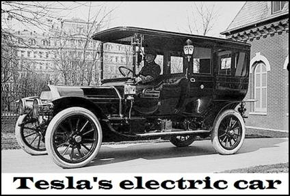
A major drawback of this converter is that it has to be excited. And the Tesla-built version did not need a signal generator (alternator). The version built into his car was self-excited. All it needed was an antenna. The signal was provided by the ether noise collected by the antenna. This could presumably be any movement that disrupts the smooth flow of the subatomic energy particles that make up the aether. Such an effect could be caused by sound vibrations in the air, wind, vehicle motion, rain, lightning or any mechanical change of position that might occur on a living planet. To this must be added electromagnetic emissions (radio waves, signals emitted by television transmitters or mobile phone signals). However, these are not included in the excitation because the valve diodes of the converter exclude harmonic electromagnetic waves from the excitation. The Tesla converter collects neither the excess energy nor the excitation energy from nearby transmitters. It uses only longitudinal waves.
The signal from the cosmic background radiation is not large, but it is sufficient to compensate in the input stage for the loss due to the thermal motion of the electrons as they collide with each other. In the following stages, this is no longer a problem, because after the energy has accumulated and the voltage has been transformed, this loss plays a negligible role. The existence of ether noise is easily verified by turning on the radio or television. If you tune your radio between two stations in the VHF band, you will hear a hissing sound. This is the ether noise. On television, we can also see ether noise, also known as cosmic background radiation. If we stray to a channel that is not broadcasting, we also hear a hissing noise and black and white dots appear on the screen in chaotic motion.
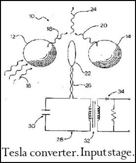 In his
patent specification, Tesla also provided a circuit diagram of the input
stage. But he did not describe the frequency at which it should be tuned.
Therefore, we have to measure the frequency of the ether noise and tune the
resonance frequency of the first and subsequent stages to this value. For
tuning, first use an Esaki or backward
diode. If the threshold voltage of
this diode is too high, and therefore
the few milliwatts of energy that can be extracted from the wire antenna cannot pass through it, then the n-type
field diode suggested above should be
tried. In principle, this has a
threshold voltage close to zero. The creation of this diode was a problem from the very beginning. All we know about the diode material is that
Moray experimented with germanium, molybdenum sulphide and bismuth crystals in the 1920s and 1930s. The degree of
doping must have been important, because he was constantly concerned to clarify
the chemical composition of the crystal. This suggests that this particular
device was a rudimentary tunnel diode based on germanium. Tesla also used a
cold-cathode electron tube for this purpose. (If fabricated in miniature, this
component would take up no more space than a discrete transistor.)
In his
patent specification, Tesla also provided a circuit diagram of the input
stage. But he did not describe the frequency at which it should be tuned.
Therefore, we have to measure the frequency of the ether noise and tune the
resonance frequency of the first and subsequent stages to this value. For
tuning, first use an Esaki or backward
diode. If the threshold voltage of
this diode is too high, and therefore
the few milliwatts of energy that can be extracted from the wire antenna cannot pass through it, then the n-type
field diode suggested above should be
tried. In principle, this has a
threshold voltage close to zero. The creation of this diode was a problem from the very beginning. All we know about the diode material is that
Moray experimented with germanium, molybdenum sulphide and bismuth crystals in the 1920s and 1930s. The degree of
doping must have been important, because he was constantly concerned to clarify
the chemical composition of the crystal. This suggests that this particular
device was a rudimentary tunnel diode based on germanium. Tesla also used a
cold-cathode electron tube for this purpose. (If fabricated in miniature, this
component would take up no more space than a discrete transistor.)
When reviving the input stage, it should be remembered that this circuit, even using a zero threshold voltage diode, does not supply enough voltage to revive the additional stages. The ether noise can only cover the loss in the LC circuit. To turn on the converter, a starting pulse is required as mentioned above. In other words, a voltage must then be applied to the input stage for a pulse that far exceeds the signal level provided by the ether noise. After that, the continuous excitation can be provided by the antenna. Tesla used external magnetic excitation for this purpose. Presumably he inserted two magnet rods of opposite poles into the system, while Moray used a horseshoe magnet to "caress" a component covered with black tape. In all probability, this unit was a coil that, when magnetically excited, was capable of inducing a voltage sufficient to bring the circuit to life, providing the initial voltage needed to start it.
However, at the current state of electronics, this problem can be solved more elegantly. The simplest way to construct an inductor connected to the first stage is to use an electric pushbutton. Attach a small bar magnet to the end of its shaft and place a solenoid made of enamelled copper wire around it. When the push-button is pressed, a voltage is induced in the coil that can revive the converter. Since piezoelectric crystals did not exist at the beginning of Tesla's work at the end of the 19th century, it would be worth putting a small piezoelectric coil behind the push-button shaft. (Beware of using piezo igniters in lighters, used in gas stoves and built into gas convectors. These are fitted with multiple coils stacked on top of each other and the thousands of volts they generate will short-circuit the converter. (The output voltage of a gas stove igniter is 15 kV.)
The output transformer must be designed to transform several kilovolts of voltage to an effective voltage of 230V (110V). This raw electricity is already perfectly suitable to power a heating coil (radiator, electric stove, water boiler). To ensure that the pulsating direct current does not interfere with nearby communications equipment, the output voltage can be smoothed by a high-capacity electronic capacitor. Before doing this, there is one more thing to try. If we introduce current in the form of soliton waves into the heating elements, the aether in the heating filament will also help to multiply electrons.[8] This means that the heater cartridge can handle less current, with a smaller converter attached. For fire safety, the converter should not be left switched on when not in use. The easiest way to turn it off is to ground its antenna. For this purpose, an additional push button should be fitted on the front panel. If a soliton signal generator is used, the generator power shall be switched off.
The finished converter only needs to be protected against short-circuits. Without it, the converter would overheat and burn out in the event of a consumer short circuit. In the event of overload, one of its components would fail. The simplest and cheapest solution for short-circuit protection is a fuse. However, this is not recommended, firstly because it increases the internal resistance of the power supply, which impairs the stability and load capacity of the converter. More importantly, in the event of a short circuit, the user does not have a spare fuse, so the blown fuse is "blown". This will cause the converter to burn out. Recognising this danger, households have already stopped using fusible links. Nowadays, all homes have a circuit breaker that will trip in the event of a fault. In this case, all you have to do is to remove the short-circuiting device and then turn the circuit breaker back on.
The disadvantage of the circuit breaker is that it also increases the internal resistance of the power supply and is not fast enough. The tripping is done by an electromagnet with the mains current flowing through the coil. In the event of a short-circuit, the electromagnet pulls a trip wire, which breaks the circuit. Instead, the parallel short-circuit monitoring circuit that I have invented should be used. None of its sensing elements are in series with the supply current, so it does not increase the internal resistance of the power supply. Another big advantage is that it has no reaction time. Since the electromechanical switching element is tripped by the opening contact rather than the closing contact, the response time of this overload protection circuit is zero. Its manufacturing cost is no higher than the purchase cost of a relay. The invention entitled Short-circuit protection (Controllable electromechanical overcurrent and short-circuit protection for any type of power supply) can also be downloaded from the Kun Electronic Library.
 For high power Tesla converters of several
kilowatts, it is not necessary to use a large relay. Inexpensive, small relays can also be used for
disconnection. In this case, the antenna must be grounded or the signal
generator supply voltage must be interrupted in case of overload. A hermetically
sealed reed relay is ideal for this purpose. In cars or aircraft subject to
vibration, however, the use of mechanical switching elements is risky. They can
shake (bounce). There is also a risk of contact chafing due to outdoor use.
Therefore, in this case, it is advisable to incorporate a varistor in the
stabiliser supplying the signal generator, which will cut off the signal
generator supply in the event of a significant output voltage drop. In the
absence of a signal generator, the Tesla converter will shut down, which does
not happen immediately. The supply voltage drops to zero only after a few
tenths of a second, because the energy in the capacitors must be burned out
through the load.
For high power Tesla converters of several
kilowatts, it is not necessary to use a large relay. Inexpensive, small relays can also be used for
disconnection. In this case, the antenna must be grounded or the signal
generator supply voltage must be interrupted in case of overload. A hermetically
sealed reed relay is ideal for this purpose. In cars or aircraft subject to
vibration, however, the use of mechanical switching elements is risky. They can
shake (bounce). There is also a risk of contact chafing due to outdoor use.
Therefore, in this case, it is advisable to incorporate a varistor in the
stabiliser supplying the signal generator, which will cut off the signal
generator supply in the event of a significant output voltage drop. In the
absence of a signal generator, the Tesla converter will shut down, which does
not happen immediately. The supply voltage drops to zero only after a few
tenths of a second, because the energy in the capacitors must be burned out
through the load.
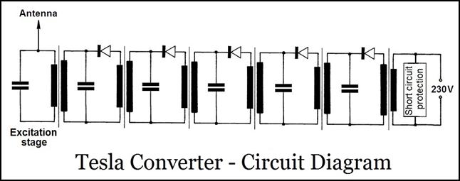
As can be seen in the circuit diagram above, the parallel LC circuit formed by the secondary coil and the capacitor connected in parallel with it is powered not by the galvanically connected power supply, but by the primary coil. The feeding is done magnetically and by induction. That is why it is necessary that the mass of the primary and secondary coils be the same. If the primary coil had a smaller mass, it would not be able to take advantage of the magnetic conductivity and coercivity of the iron core. The role of the diode is to prevent the windings from affecting each other. Another role is to prevent the formation of an electromagnetic vibration circuit between the individual stages. Energy can only flow forward, not backward. This is what Tesla called valving. However, this is only possible if the diode has no reverse current, because this allows the secondary winding of the previous stage to have a shunting, exciting effect. The energy produced by longitudinal waves is cumulated (added up). It does not go back and forth in a parallel vibrational circle until it is consumed by the force of friction. There is no oscillation in the special vibration circuits of the Tesla converter. Here the energy is charged and moves from stage to stage. Meanwhile, as a result of the resonance, it gets stronger by degrees.
Once the Tesla converter is reconstructed, manufacturers of electronic devices will most likely switch to converter power. They will incorporate a Tesla converter in their products, sized to match the power consumption of the device. However, they cannot do this with the appliances they have previously produced and sold. They still have to be powered from an external power supply. It will also take 10 to 15 years before the communication equipment, jukeboxes and computers currently in use become obsolete and are replaced. However, mains electricity is not needed to power these devices either. For this purpose, a portable or wheeled converter should be provided, which should be supplemented by an inverter. The inverter converts the pulsating direct current into alternating current of 230 (110) volts at 50 (60) Hz. This portable converter is likely to be used for a long time in the long run, because it is not possible to install the converter in hand-held appliances (e.g. hair dryer, electric shaver). This would increase the size and weight of the device to an extent that would make it unmanageable. However, it is conceivable that manufacturers could include an adaptor with their portable devices that contains a mini Tesla converter. As with charging adaptors for mobile phones, these small converters could be standardised to be used with any type of device from other manufacturers. So for both hairdryers and electric shavers, make only one type of adapter.
Aircraft designers are also waiting for the Tesla converter like the Messiah. Unlike electric cars, converting aircraft to electric propulsion is impossible at the current level of technology. This is due to the low energy density of lithium-ion batteries, i.e. how much energy they can store per unit mass. For the most advanced batteries available today, this value is 400 Wh/kg. In contrast, kerosene, the fuel used to power aircraft, has an energy density of 12 000 Wh/kg. That is, it contains thirty times as much energy. The take-off weight of a B737 passenger aircraft is min. The maximum take-off weight of a B737 aircraft is 80 tonnes. Of this, 21 tonnes is kerosene. To replace that much kerosene, 630 tonnes of batteries would be needed. With this extra weight, the aircraft would not be able to take off.
The situation is not much better for hybrid aircraft. In this system, a gas turbine on board generates electricity to power the electric motors of the propeller-driven aircraft. Since a propeller-driven aircraft can use only 20% of petrol and the electric motor is more than 80% efficient, the 30-fold weight gain can be reduced by a factor of ten. However, this also requires a split propulsion system, cryocoolers and superconducting engines. This in turn makes the production cost of the aircraft significantly more expensive. Airlines would even accept this, but the tenfold increase in fuel would reduce the range of their aircraft by a tenth. This would mean that intercontinental flights would be eliminated. Even within a continent, passengers would only be able to get from one country to another with multiple connecting flights.
Another problem is the speed reduction. A propeller-driven passenger aircraft can fly at around 600 km/h, compared with 900 km/h for the jet passenger aircraft currently in use. (The Boeing 787 Dreamliner can briefly exceed the speed of sound, i.e. 1225 km/h.) And the Concorde jet aircraft had a maximum speed of 2,754 km/h.)[9] The almost halving of the airspeed would double the journey time, which would not please passengers. The best solution would be an antigravity engine. It would need no fuel[10], weigh negligible compared to the weight of the vehicle, cost minimal to produce and have a maximum speed of 72 000 km/h at 32 km altitude after leaving the airspace. The only problem is that nobody believes it is feasible, so nothing is being done to make it happen.
With the development of the antigravity engine, road and sea freight transport will be shifted to the air. But this will take decades. In the meantime, cruise ships and cargo ships would have to be converted to electric propulsion. In these monsters, diesel engines consume 300-400 tonnes of gas oil a day. So the fuel consumption of a single container lorry is equivalent to that of about 50,000 cars. It is estimated that at least 100,000 of these are constantly sailing the seas, transporting goods from one continent to another. This means burning 35 million tonnes of diesel every day. This means that cargo ships alone consume eight times more fuel than the world's passenger car fleet combined. Multi-decker cruise liners consume similar amounts of fuel to container ships, and there are at least a few thousand of them on the water. To sum up, mega-cargo and passenger ships at sea consume ten times more fuel than the world's total passenger car fleet. And that's just the consumption!
In terms of pollutant emissions, the situation is much worse because passenger cars use less polluting refined petrol and diesel. Container trucks, on the other hand, use the worst quality diesel oil, which is very high in sulphur. While sulphur emissions from cars are strictly regulated, the limit for marine fuel is four thousand times higher. So while their carbon dioxide emissions are only ten times higher, their sulphur dioxide emissions, which are extremely harmful to health, are 40,000 times higher than those of all the world's cars. In terms of sulphur emissions alone, a cruise ship emits as much sulphur dioxide as 200 million cars.
The situation is not much better for passenger aircraft. On average, they consume between 4 and 10 tonnes of kerosene per hour, which translates into an average of 200 tonnes of fuel per day. Statistics show that an average of 25,000 passenger and cargo aircraft are in the air at any one time. Their total consumption is 5 million tonnes of kerosene per day. This is just the equivalent of the daily consumption of all passenger cars.
When developing the circuit board model, avoid the plug-in, flying lead connections that are fashionable nowadays. When these miniature banana plug wires are connected, a contact potential occurs which prevents the transmission of signals of a few millivolts. In addition, both the plug and the sleeve can corrode, leading to contact failure. Instead, use a classic modeling board with a tubular rivet. Drill a 2 cm square hole through a 4-5 mm thick textile bakelite plate, insert a 3-4 mm diameter copper rivet into each hole, bend the other end back with a dowel and hammer, and run a soldering iron through it. Screw a plastic foot into each of the four corners of the textile baking sheet to avoid burning the table during soldering. Solder the legs of the components and the connecting wires to these tin-plated pipe rivets. Use insulated cable twisted from hair-thin tin-plated copper wires as connecting wire.
Also ensure that the soldering iron is clean. Always have a piece of resin next to the soldering iron, and prick it to remove the reed from the tip of the iron. Only use a resin soldering iron for soldering. To protect the components, the soldering iron should not be used with an operating voltage of more than 12V. When selecting components, use good quality foil capacitors (e.g. stiroflex, polypropylene, epoxy resin). Since the electrolytic capacitor is polarized and has a high leakage current, its use should be avoided.
Once the board model is operational, it is time for technology and industrial design. The components must be mounted on printed circuit boards or on a base plate made of thick textile bacelite, and the transformers must be placed on it so that their mass is balanced in the coffee. In this way, the converter will not tip over when lifted, and moving and transporting it will not be an accident hazard. For reasons of protection against contact and to avoid spillage with communications equipment, the apparatus shall be enclosed in a soft iron case approximately 1 mm thick, with a threaded stub welded on the back. Grounding can be carried out by means of this threaded bushing fitted with two nuts and a spring washer. The inner metal casing can be covered by a plastic housing with a design. This should be moulded from unattractive polystyrene, which is fragile. Polycarbonate is not good either because it is expensive. PVC is best because it is cheap and flexible.
After making it, you need to test whether the Tesla converter emits magnetic radiation. The easiest way to do this is to use a compass to approach the grounded metal housing. If there is significant magnetic emission, this should be noted in the instructions for use. In this case, the situation is complicated because you need to check how much this affects your health. Unfortunately, magnetic radiation cannot be shielded because etheric particles penetrate all materials. If the radiation is strong, there is a "mouse path" for us.[11] Set the frequency of the soliton wave to 28 kHz. At this frequency, the etheric radiation has a healing effect on the body. (Keeping animals at home will also be a problem, because animals have an alpha brain frequency and are therefore very sensitive to magnetic radiation. In this case, our civilisation will have to decide what is more important, the environment, brain energy or the keeping of dogs, cats and other pets.)
Since the Tesla converter is a revolutionary esoteric device in our world, it is likely to be looked upon with aversion and fear. To reassure consumers, the following text should be included in the instructions for use:
The Tesla converter harnesses the kinetic energy of electrons flowing in parallel LC circuits, with transformer spin-off. The excess energy is due to the amplification effect of the rectifier diodes of the 12 stages, which is due to the negative internal resistance. To this is added the additional energy from soliton excitation and the tuning of the last stage to resonant frequency. Since the operation of this generator is based on a well-known basic electrical circuit, the parallel LC resonant circuit, the device does not emit electromagnetic, radioactive or other harmful radiation. Its use does not involve any harm or danger. There is even no risk of electric shock on earthed mains power lines. However, it is strictly forbidden to touch the output terminals at the same time, as this generator also supplies the same voltage as the mains lead. Therefore, the consequences of electric shock resulting from inattention or carelessness are the same. Nor is it less current-carrying than the mains supply. The Tesla converter is therefore capable of supplying the entire power supply of a family house.
The reconstruction of this converter will certainly revolutionise the world's energy supply. As the cost of producing Tesla converters is low, there will be no need to consolidate energy in buildings within each municipality. In fact, because they are cheap to produce, they can be used to power each individual consumer with a separate generator. The power circuit can also be built into the consumer's appliance housing. This eliminates the need for power cords. This also eliminates the electrosmog emitted by the power cables running through the room. So this power supply system not only provides free electricity, it is also good for your health. As these converters have no moving parts, they require no maintenance and cost no more than the purchase price of an average household robot, they can be used to provide individual power supplies for homes without any difficulty. In this way, not only high-voltage transmission lines can be eliminated, but also the electrical interconnection cables within a municipality can be eliminated. This will save countries and citizens a huge burden and expense.
In our domestic context, the Paks nuclear power plant currently generates electricity for HUF 8 per kW. This is passed on to consumers by the electricity companies for 42 cents. What is the point of paying a 500% premium for electricity when it can be produced locally, and for free. It is completely unnecessary to build and maintain thousands of kilometres of high-voltage and low-voltage transmission lines, thousands of transformer stations and then install millions of electricity meters to measure consumption. Not to mention the fact that centralised electricity supply can be cut off at any time. Storms or ice can tear down power lines, fallen trees can damage local overhead cables, and lightning strikes can burn out high-voltage transformers. Underground cables are not safe either, as they are torn up by road construction and maintenance machinery. There is also the danger of wiring up buildings. Worldwide, thousands of industrial plants and homes burn down every year due to partial damage caused by poorly installed cables.
Just as much trouble and just as dangerous is the maintenance of thousands of kilometres of gas pipelines, which is also unnecessary. If sufficient electricity is available, the use of relatively cheap gas is unnecessary. The gas pipes will be removed from the walls of your buildings along with the electricity, giving your houses back their natural appearance. (With the switch to electric heating, there will be no need to build chimneys on the roofs of your houses.) There will be no more gas explosions, no more fires caused by electrical blackouts. By dismantling radio, TV, mobile phone and other microwave towers[12] and removing power lines, the landscape will be more beautiful and our neighbourhood more liveable. The harmonious landscape of thousands of years ago will return without having to give up our civilisational achievements. And with the end of power stations, explosive vehicles and fossil fuel heating, global warming will stop and, in time, nature will regenerate. The Earth's mineral reserves will not be exhausted prematurely either, as millions of tonnes of easily smelted iron and copper are produced from dismantled power lines worldwide, providing decades of raw material for industry.
The Tesla converter could also help to overcome water shortages. (Only three percent of the earth's water supply is freshwater, and even four-fifths of that is used for agriculture. That means that nearly eight billion people share less than half a percent of the total global water supply.) Developing countries already face a shortage of clean water. In coastal countries, fresh water is produced from seawater. But this process has not become widespread because it is very expensive. Filtering the water by osmosis requires electricity, which is expensive. (4.5 kilowatt-hours of electricity are needed to produce 1,000 litres of water.) Distillation is also very energy-intensive. However, the energy generated by the Tesla converter is free, which allows distillation to be used on a wide scale. (The latter process does not require an expensive membrane filter.) Boiling water with the Tesla converter also eliminates pollution because it does not require power plant electricity. Fossil fuels will not be needed either (Saudi Arabia currently uses one and a half million barrels of oil a day to power its desalination plants.)
(71% of the Earth's surface is covered by seas and oceans, at an average depth of 3 km.) In the future, there will be no obstacle to transporting desalinated water over long distances. With the disappearance of gas and oil transport due to free energy, the remaining pipelines will be able to transport fresh water to the interior of continents. Europe will also need this, because global warming will cause the glaciers in the Alps to melt, drying up rivers in the summer and cutting off the water supply to large cities. This could even cause a pandemic. Just think what would happen if Budapest's water supply were to be cut off overnight. (This could easily happen, because our capital is almost entirely supplied by the Danube. Without water, it would be impossible to bake, cook, wash dishes, do the washing up, water the garden. 2 million people would not be able to clean themselves, nor would they have enough water to flush the toilet. In a matter of days, this would create an epidemic risk so great that the entire capital would have to be evacuated. (The entire stretch of the Danube currently supplies tap water to 20 million people, and is the source of drinking water for many.)
[
The Tesla converter is a very useful thing, but we can't use it everywhere. Today, everything is over-miniaturised and the "flat" mania is raging. Not just smartphones, but televisions, computer monitors, and more recently notebooks, are getting flatter. A 7-8 mm thick device will not fit a Tesla converter's fist-sized output transformer. An electronic converter would be needed to power these devices. A circuit consisting of semiconductors or flat capacitors at most. An electronic transformer capable of transforming the weak signal from the input stage of the Tesla converter without an inductor (transformer). Sooner or later someone will invent this converter.
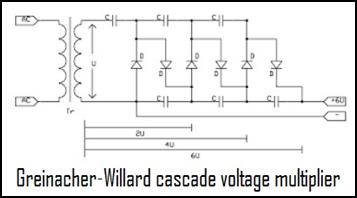
In the meantime, it might be worth looking at the Greinacher-Willard connection. The cascade voltage multiplier diodes and capacitors can be used to increase the connected voltage to any value. Increasing the voltage supplied by the input stage of the Tesla converter by a few millivolts to several volts is therefore not a problem, but it does not increase the power. Soliton feeding is not an obstacle here either. Although the Greinacher-Willard circuit requires an AC supply, a signal generator can also be used to produce a halved sine wave, or soliton, signal from a regular sine wave. A Graetz rectifier bridge is then connected to the end of the converter to convert the AC current into DC current. The pulsation of the current can be eliminated by a high-capacitance electronic capacitor. The use of field diodes is not an obstacle here either, so it is likely that a large amount of excess energy can be extracted from this converter.
 If the energy multiplied up to 5V for smartphones
or 12V for notebooks is not sufficient to power
the device, the voltage will have to be multiplied further, increasing
the number of rectifier bridges connected in the cascade. In this case the output voltage can be several hundred volts. To reduce
this, a transformer would be needed. This does not fit in the device. There is, however, a workaround, the
switching power supply. Until about 1990, the power supply for computers
contained a soft-iron transformer weighing
several kilograms. Then came the switching power supply, which,
despite delivering 500-600 W of power, is almost as light as a feather.
If the energy multiplied up to 5V for smartphones
or 12V for notebooks is not sufficient to power
the device, the voltage will have to be multiplied further, increasing
the number of rectifier bridges connected in the cascade. In this case the output voltage can be several hundred volts. To reduce
this, a transformer would be needed. This does not fit in the device. There is, however, a workaround, the
switching power supply. Until about 1990, the power supply for computers
contained a soft-iron transformer weighing
several kilograms. Then came the switching power supply, which,
despite delivering 500-600 W of power, is almost as light as a feather.
 This is made possible by the fact that the transforming
is not done at 50-60 Hz but at 20-50 kHz. The
mains voltage is first rectified and then buffered (stored in a capacitor,
smoothed). It is then clipped using
a transistor. The current, with a frequency of about 30 kHz, is then passed
to a pulse transformer. The voltage coming off the secondary winding
is rectified by a fast switching Schottky diode, then filtered and buffered.
Finally, the voltage regulation electronics
follow. This also works differently from linear voltage regulators
because it is done by varying the pulse width. (The higher the power load, the wider the pulses applied to
the transformer.)
This is made possible by the fact that the transforming
is not done at 50-60 Hz but at 20-50 kHz. The
mains voltage is first rectified and then buffered (stored in a capacitor,
smoothed). It is then clipped using
a transistor. The current, with a frequency of about 30 kHz, is then passed
to a pulse transformer. The voltage coming off the secondary winding
is rectified by a fast switching Schottky diode, then filtered and buffered.
Finally, the voltage regulation electronics
follow. This also works differently from linear voltage regulators
because it is done by varying the pulse width. (The higher the power load, the wider the pulses applied to
the transformer.)
The design of a switching power supply may seem complicated compared to a linear transformer, but it has one big advantage. Since the voltage transformation is done at high frequency, a much smaller iron core is needed. Even in the power supply of a high-performance desktop computer, there is only a tiny ferrite-core transformer. Since a notebook consumes one tenth of the power of a desktop computer and a smartphone one hundredth, the size of a ferrite core or ferrite ring transformer can be further reduced. Small enough to fit in a small flat box. It is advisable to use a flat or planar iron core. In this solution, the coil can be formed on the printed circuit board by etching it into the copper foil. The printed circuit coil itself has very low inductance. And the planar iron core placed on it thickens it considerably. Today, however, iron core coils are also produced in printed circuit design. In this solution, a ferromagnetic layer is applied to the inner layer of the substrate using nanotechnology. Using a double-layer substrate, this process can also be used to create a toroidal coil in printed circuit form.[13]
Another major advantage of voltage conversion with a switching power supply is that while conventional transformers made of soft iron plates have an efficiency of up to 85%, switching power supplies can have an efficiency of more than 95%. However, the real size and price reduction is not achieved with this, but with the voltage stabilisation circuit that follows. While the voltage of a plate transformer can only be stabilised using a series valve transistor process, this is much easier to achieve with switching power supplies. As the load increases, only the width of the switching signals needs to be increased, with no loss of power. The valve transistor solution requires a much higher input voltage to stabilise the output voltage. The difference between the two voltages generates a significant excess power in the stabilizer, which is dissipated by the valve transistor, converting it into heat. For this reason, the efficiency of linear power supplies is only 40 %. Another factor contributing to its size reduction is the absence of a heat sink, which protects the valve transistor from overheating in linear power supplies.
Since the permeability of a ferrite iron core is much lower than that of a soft iron core, many may wonder how it is possible to make a power supply with much better efficiency than soft iron transformers.[14] This is because, unlike a soft iron core, a ferrite core can be excited at high frequencies, up to several hundred kHz. This has made it possible to create small and cheap switching power supplies. Yes, but increasing the operating frequency alone does not increase the efficiency of the transformer. This is already happening in switching mode power supplies. So much so that their efficiency exceeds that of soft-iron transformers. This is due to the high frequency excitation. It is very likely that, as with soliton excitation, ethereal particles enter the copper coil when the square wave excitation is used. As the square wave propagates, the interatomic space is emptied and filled by aether ions. These collide with the copper atoms, separating significant amounts of free electrons from their outer electron shells. The higher the frequency, the more they irritate the copper atoms. The resulting extra electrons increase the efficiency of the ferrite-core transformers. (If this is proven, scientists will be struck by the fact that the ether they have declared non-existent is already involved in the transformation.)
Now there is only one unpleasant side effect of using a Tesla converter: the antenna. Tesla used an antenna 2,5 meters long, while Moray used an antenna 150 meters long. When used in a car, stretching out the 2,5 metre insulated copper wire is not a problem. For electronic devices, however, it is a problem. It is useless to get rid of the mains cable if the Tesla converter's antenna is still hanging out of it and cackling along the wall. And with mobile phones, it is particularly dangerous to drag a 2,5 metre long cord behind you. A solution would be to wind up the antenna and hide it inside the casing. Wrapped around the inside wall of the cabin, it would not take up much space. The question is whether the converter works this way. It would probably not detect enough ether noise in this form. Therefore, it would definitely have to be switched to signal generator excitation.
The most ideal way to do this would be to use a signal generator that does not require any power supply and does not need an antenna. It emits energy from itself, which can then be used for excitation. This could be a crystal. Unfortunately, there is no crystal in nature that can do this. There are radiation sources, but they are not suitable for us. Radioactive isotopes emit very high energy, but they are both dangerous and electrically useless. The alpha, beta or gamma rays they emit cannot induce a current in the electromagnet. However, the situation is not hopeless. Esotericism, which is anathema to official science, can help us out of our predicament. The solution is quite transcendental, but we should get used to the idea that in the future science, religion and esotericism will merge and become a highly effective common science.
We were at the point where we needed a crystal that emitted magnetic energy. We would just have to surround it with a solenoid or put it in a toroidal coil and the electromagnetic energy induced by the crystal could be conducted out of it. But we do not have such a natural crystal. There is a crystal with magnetic emission (e.g. magnetite), but it is a permanent magnet. And permanent magnets can only induce when they are moved. We need a crystal that pulsates. No one has ever heard of such a crystal, but it exists. We just don't know what it pulsates and why. Those familiar with the esoteric literature will be familiar with the reports of the Bosnian pyramids. They mention that inside one of the 30,000-year-old pyramids is a huge stone weighing 800 kg. This disc-shaped stone, called Megalith K-2, emits positive magnetic radiation at a frequency of 28 kHz. Therefore, anyone who lies on this stone will, after a while, be charged with etheric radiation, which will make them feel better. And after repeated use, you will be cured or your illnesses will become bearable.
We should investigate what is emitting the health promoting or disease healing 28 kHz frequency. Is it the stone block or the source of the radiation underneath? We also have such an etheric radiation source in Tápiószentmárton on Attila Hill. Many people come here for healing. The famous Hungarian miracle horse, Kincsem, was filled with positive energy here. His owner rested him here between two races. On his way home, he lay down on Attila Hill next to his stable to recharge. It was due to the ethereal energy that he was entered in 54 races and won all 54. Unfortunately, you can't climb down in these places to find the source of the radiation. Most likely, we wouldn't find it either, because these rays are created by a geological anomaly from deep within. A lava flow or the intersection of the earth's dragon lines can trigger such radiation. And we can't mine that in crystal form.
In the past, we would have had easier access to devices that emit magnetic radiation. By examining them, we could have found out what makes them radiate. We know from the Bible that Noah was given a "luminous stone" by God to keep him from having to light a fire in the darkness of the ark.[15] And medieval records mention everlasting lanterns. In 1401, the tomb of the son of the former king of Troy was excavated and a lantern was found still burning. King Pallas of Troy lived in the 12th century BC. The lamp had therefore been burning for 2400 years. In 1539, a lamp that had been lit for 1200 years was also found in a Catholic church in England. The curious find was reported to King Henry VIII, who believed the ever-burning lamp to be a Roman pope's trick and had it destroyed. So we cannot examine this one either.
The last ever-burning lamp was found by a Swiss soldier, Du Praz, near Grenoble, France. He took it to a monastery, where it was studied for months, but no one could find out what kept it burning for so long. The level of oil in it did not decrease over time. Eventually, one of the monks dropped it and the oil spilled out, along with the hope of a solution. It is no coincidence that the monks never found the secret of the everlasting. After all, these lamps were not lit by flame. A reference to this is found in the Bible. In the third book of Leviticus it says: And thou shalt command the children of Israel to bring thee pure oil of olives for the laver, and to put thereon the „ever-burning lamp”. The ever-burning lamp must have been some kind of subatomic energy emitter that ionized the air and it glowed. As we know, the amount of subatomic energy locked up in matter is almost infinite, so it is not at all far-fetched to say that these lamps were ever-burning.
Despite all the failures, our situation is not hopeless. It is true that we do not have pulsating magnetic crystals, but civilisations more advanced than us do. We don't have to go far to get it. We don't have to contact extraterrestrials, because the Atlantean civilisation already had that. The people rescued from Atlantis, which sank into the ocean, moved underground and into the depths of the sea. Now they live in an artificial bubble world, on the site of their former continent. Their old world has not disappeared without a trace. It has just sunk to the bottom of the ocean and been washed away by the mud. Their huge pyramids are covered in mud, but they still function. That's what's causing the anomalies over the Bermuda Triangle.
Many people have heard of mysterious disappearances in this area. These are not annihilations, but time travel. Their largest pyramid, 300 metres long and 200 metres high, emits a powerful magnetic radiation that causes time dilation. This was the phenomenon experienced by the passengers of the passenger plane that arrived half an hour early. When they landed, they were surprised to find that their watches were invariably half an hour late compared to the airport clock. They could not be accused of imagination, because they found that the aircraft had enough excess fuel to last half an hour.
The journey of flight 513 took longer than that and did not end so happily. The passenger aircraft took off from Santiago airport on 4 September 1954. A total of 91 people were on board the flight to Germany, but they never arrived at their destination. Radio contact with the plane was lost over the Bermuda Triangle and no news has been received since. For 35 years. But on 12 October 1989, it appeared in the sky over Porto Alegre Airport in Brazil. Air traffic controllers were shocked when they identified the plane, which had been missing for 35 years and had been circling the airport for 35 years, and could not be contacted. After the plane landed, the authorities went to the runway and then on board, where they found the skeletons of passengers and crew. Anthropological examination found that their bodies had started to decompose when the plane returned to the present, and that the passengers and crew had suddenly aged 35 years. Interestingly, everyone sat in the same place they were originally supposed to.
This rapid ageing is not a unique phenomenon. It has happened elsewhere that, in almost minutes, someone has aged so much that they have died and their body has been mummified. In November 1961, a 48-year-old clerk, David Lowe, and his wife in Darlington, in the north of England, were unsuspectingly watching the evening television programme when she became bored and went upstairs to her bedroom. Lowe, however, watched the film through and did not follow her until an hour later. Not wanting to wake his wife, he undressed in the dark. He was about to go to bed, but he was suspicious of the deep silence and the fact that he could not hear his wife breathing. He had a strange feeling and turned on the light. He saw a horrible sight. His wife was no longer alive. His shock was heightened by the fact that it was obviously no ordinary death. Her body was brown and shrivelled. The terrified husband found a mummy in the bed. Her missing teeth were protruding from her open mouth. The teeth that had fallen out were later found in her mouth.
The police and the coroner also discovered other anomalies in the bedroom. They found blackened plant fibres in her flower vase, which may have been the remains of a bouquet of flowers she had placed in it the day before. The bed linen and furniture covers also bore the marks of a long period of time, even though the Lowe's had bought new bedroom furniture the year before the incident. It was also noticed that the floor and the furnishings were covered with a thick layer of dust, which takes decades to settle. This could not have formed in the past because she vacuumed the room every day. The husband recognised the dead woman as his wife, although the 42-year-old woman looked more like her own grandmother. The autopsy concluded that the deceased was an 85-90 year old woman who had lain unburied for several years after her death, her body mummified in the dry air. The husband had no idea how his wife could have aged 30 years in just 1 hour while she slept. She then died and was mummified without either he or the neighbours noticing any abnormalities in the area.
Going back to the crystal pyramids of Atlantis, the aircraft that flew over the top of the pyramid experienced a much greater time dilation. They were transported back in time to the world of Atlantis. The disappearances began in 1945, with the case of the 19th military unit. On December 5th, six military planes took off from Florida. An hour later, each pilot reported to headquarters that they were lost and did not recognize the landscape below. The control tower recorded the conversation with the pilots. One of them said, "My navigation instruments are going crazy. The compass is spinning round and round. The sea has changed. I can see a landmass that shouldn't be here, because according to my chart and my knowledge of geography, there are no islands. In comparison, there is a green continent below me." Their instruments then became completely inoperable, and they were unable to control the distressed aircraft from the tower. One of the rescue aircraft sent after them also disappeared during the search. It was probably searching over the pyramid. In the days that followed, hundreds of ships and planes searched nearly 250,000 square miles of the Atlantic and Gulf of Mexico, but neither the 27 victims nor the wreckage were found. Records since 1851 show that 8127 people have been lost in the Bermuda Triangle. In addition, more than 50 ships and 20 aircraft have disappeared without a trace.
Such time travel also occurs in pyramids in our world. In villages near the pyramids in Egypt and Bosnia, parents have been warning their children for centuries not to play near the gulas. Their fears are not unfounded, as several children have disappeared without a trace in the vicinity of the pyramids in the past. They have never been found. Residents of nearby Bosnian villages say they see strange lights flashing near the pyramids at night. Arab children are warned of the same by parents living near the Great Pyramid. According to one traveller, he became dizzy near the dome and suddenly found himself in another world. Gone was the pyramid, gone was the Sahara, and he found himself on a strange beach, where seagulls screeched and green waves lapped the piers and boats. Further inland from the shore, he saw a straight street leading into the interior of the island. There were streets paved with marble, where people in white dress walked among palaces built of crystal. He was about to go into the city to have a closer look around when he was back in the Sahara in an instant. In the sandy desert, he was saved from dehydration by being found by a caravan.
According to a medieval Bosnian adoma, some children once disappeared near the Pyramid of the Sun. Their parents searched the area for months. They had given up on them, mourned them, when suddenly they turned up. They were wearing the same clothes they had disappeared in, and they hadn't lost any weight. When questioned, they said they were playing by the pyramid when they saw an opening in the side of the vegetated goula. Curious, they ventured into the cave. Once inside, however, they were frightened by the light coming from inside. But their curiosity drove them further, but they did not reach the source of the light because they suddenly felt a blow on their forehead and felt dizzy. They thought they had hit a stone wall, but the next moment they opened their eyes and found themselves on the shores of Atlantis. They couldn't understand how the sea came to be here, since no sea washes the borders of Bosnia. They too heard the screeching of seagulls and saw the ships anchored in the harbour. They don't remember anything else, because suddenly they were back. Asked what they did for the four months they were away, they could not answer. They said that when they tried to go inside the island, they got dizzy again and found themselves back in their village in an instant. They swore that they thought the adventure lasted no more than 10 minutes. Such adventures have happened in other countries. Similar disappearances have been documented at the Mayan pyramids, the Chinese pyramids and the Mongolian pyramids. It is clear that this is time dilation. This also explains the disappearances in the Bermuda Triangle.
In October 2012, American and French scientists led by Dr Verlag Meyer discovered a pyramid larger than the Kheops pyramid on the Atlantic Ocean floor. Diving underwater in wetsuits, they found that the pyramid was made of some kind of white crystal. And their instruments indicated that the top was magnetic. Visual observation showed that it was emitting some strange light. It appeared as if the top was pulsating. This is not the first time. Divers have found crystal pyramids in the ocean off the coast of the Yucatan, off Louisina, Florida, before. The most famous case occurred in 1970, when an amateur diver, Ray Brown, got lost while diving off the Bahamas. Thirty kilometres off Berry Island, he became separated from his companions.
While searching for them, he noticed a strangely luminous pyramid-like structure in the ocean 30-40 metres below the surface. He said the pyramid was at least 100 metres high and covered with a perfectly smooth, crystalline material. The pyramid glowed with a slight glow, turning the otherwise pitch blackness milky white. Brown discovered two openings in the pyramid, and through one of them he entered the interior, where he found a completely clean room, free of all marine plants and animals, the walls of which also glowed with a vague whiteness, like the outside of the pyramid. Inside he could swim from room to room. On the walls he saw writing of unknown origin, unlike the letters of any language on earth. Gazing around the pyramid, he had a sense of presence all the time, as if the guardian of the pyramid were watching him.
When he left, he brought with him a piece of crystal lying on the ground, which was apparently of the same material as the pyramid. This was later subjected to laboratory tests, which concluded that: 'The material of the crystal is not found on our Earth. It is not identifiable with any other crystalline material on our planet." It has also been shown to multiply the energy radiated into it in unknown ways. For example, it multiplies the light emitted into it many times over. It would be useful to borrow this crystal fragment and put it inside a toroidal electromagnet. If its pulsating magnetic discharge creates an induced voltage in the coil, then we have found the ideal excitation circuit for the Tesla converter. If the Atlantean civilisation were to reveal how this crystal was made, all obstacles to the mass use of the Tesla converter worldwide would be removed.
Budapest, 21 January 2018
![]()
Unfortunately, I haven't received any support from anyone in the last 6 years, so I haven't been able to reconstruct any of the 7 esoteric inventions. However, I was able to save enough from my half-pension to start developing an idea I had 10 years ago, resonant frequency excitation.[16] After a while, this also required more and more money, which I could no longer cover even with loans. The lack of professional cooperation also hindered the successful completion. That's why I put this development on hold. However, the remaining parts and instruments, as well as the professional experience gained during six months of work, allowed me to start reconstructing the Tesla converter. (The working mechanism of the Tesla converter is also largely based on resonance.) It won't be easy either, I've cut my ax into a big tree, but I'll do my best. My biggest problem in this case will be the lack of money. However, the necessary conditions for starting are given, and then what will happen will happen.
First, let's take a look at what we know about this device. Fortunately, Tesla has revealed the most important information about its converter. He also wrote down the details in his diary and notes, but these cannot be accessed because after his death, the FBI ransacked his poor room and took all his notes and documents for "state security reasons". They were declared top secret and to this day no one is allowed near them. However, the biggest damage was caused by a fire. When his laboratory burned down, a whole series of irreplaceable documents were destroyed. However, Tesla regularly gave lectures to the general public, where he revealed the working mechanism of his inventions. These eye and ear witnesses and the journalists present passed on what they heard. This information was not lost, and the authorities could not do anything against word of mouth.
In this way, some essential information about the Tesla converter was also preserved, which was supplemented by Tesla and Moray's colleagues. The most important of them is that the resonance in the Tesla converter creates the excess current, i.e. the free energy. The prerequisite for resonance is that the mass of the primary and secondary windings of the transformer is exactly the same gram. The secondary voltage can be transformed up or down, that is, the wire diameter of the secondary winding can be thinner or thicker, but its weight must be the same as the weight of the primary winding. Another key piece of information is that the primary coils of capacitors and transformers cannot form a vibrating circuit, i.e. transverse waves cannot play a role in the operation of the converter. (This may cause problems during development, because the principle of operation of all electrical, electronic devices, devices, and equipment in our world is based on transverse waves. It is questionable whether they will be able to detect the voltage and current created by longitudinal waves. In this way, the Italian Marconi, who stole Tesla's invention, changed his longitudinal radio transmitter and receiver to a transversal one so that his patented radio would not resemble his boss's invention.
This didn't cause any problems at the time, but it has now become clear that it deprived us of communication with extraterrestrials and otherworldly beings. They do not use transverse waves, because they do not go anywhere with their low propagation speed and a maximum range of 100 kilometers. Returning to the associated development difficulties, Tesla also revealed how to filter transverse waves from the ether. This can be done with a very simple circuit consisting of only three inexpensive components. Older professionals still remember how they made detector radios when they were children. (Young people don't know anything about this kit, because they smear their smartphones from morning to night. They don't do DIY, because they get everything ready-made from their parents.)
Well, the detector radio consists of three parts. It consists of a parallel vibrating circuit consisting of a solenoid wound with enameled copper wire and an air variable capacitor. The wire antenna was attached to it on top, and the grounding wire was attached to it below. (Regular grounding must be made from a copper plate dug into the ground, onto which the insulated, twisted copper wire that was brought into the apartment was soldered. Many people replaced this with a copper rod inserted into the ground.) The antenna was made from a 3-4 mm thick solid copper wire, one end of which was secured with porcelain insulating screws it was fixed on the roof and the other end was tied to a tree or the wall of a nearby house. The lead-off cable here was also an insulated, twisted copper wire soldered to the copper wire. The third component, a germanium diode, was soldered to the antenna-side end of the vibrating circuit.
This was the end of the detector radio, which the XX. they were used for decades in the first half of the century. Radio broadcasts were listened to with earphones with high internal resistance, which were connected to the other end of the diode and the ground wire. (This era was ended by the invention of the tube triode in the 1930s. After that, table radios with speakers appeared, which, due to their high prices, only became available to the masses in the second half of the 20th century.)
Tesla's detector radio looked essentially the same. The only difference is that he inserted the demodulator diode between the capacitor and the coil. This prevented the detection and emission of transverse waves. This circuit can only detect longitudinal waves. We will still get a lot of use out of this brilliant invention, because it is the basis of the remote monitoring device, the chronovisor and many other devices. Among other things, we can eavesdrop on the communications of extraterrestrials with it, and we can also contact civilizations that live hundreds or thousands of light years away from us. (One of them sarcastically remarked that this communication is so simple that you will never figure it out.) Well, we figured it out. Tesla invented it, but nobody needed it.
We also learned from Moray's colleague that his boss's converter consisted of 12 cascaded stages, in which the vacuum tube played the role of a diode. For this, an insulated copper wire with a diameter of 6 mm and a length of 150 m was used as an antenna, and the ground wire was connected to the water supply network. The reason it took so long was because Moray mostly used his device to eavesdrop on distant conversations. Tesla, on the other hand, used his converter to drive his car, for which a 2.5 meter long antenna was sufficient.
However, none of the inventors mentioned the resonance frequency of each stage. The reason for this is that 90 years ago there were no oscilloscopes or even frequency measuring instruments, so they could not measure it. How they were able to bring all the stages into resonance causes quite a dilemma. The resonance frequency depends on the mass. The larger the transformer, the lower its natural vibration frequency. Therefore, the Tesla converter cannot be operated with a signal generator, because where do we tune the generator. If the first stage is vibrated with it, all the others do not work. An obvious solution would be to vibrate the last, i.e. the largest, transformer, because this is where the most free energy can be expected. However, the signal required for this does not reach it. If a transformer does not vibrate at a resonance frequency, its efficiency is max. 95% This 5% loss over 11 stages will be so great that there is nothing left of the signal to excite the last stage.
However, Tesla bridged this problem in an ingenious way. He used a broad-spectrum signal source as an excitation signal. This is nothing but a sample of ether noise. Outer space is full of plasmatic, gravitational and magnetic shock waves. Pulsars, neutron stars, small white dwarfs, objects crashing into black holes. Volcanic eruptions, comet impacts, and powerful explosions on the planets. Since the extent of the universe is almost infinite, these phenomena occur continuously. This is called ether noise. Since these tumults do not occur simultaneously in the ether sea that fills the universe, their frequency is different. Sometimes they happen less frequently, which induces a lower frequency, and sometimes they occur more frequently, which induces a higher frequency. This results in a wide frequency band. If this is introduced into the converter, each stage will find the frequency that brings it into resonance. In this way, all stages start to vibrate, and at the end the energy given to each other can be measured in kilowatts.
Since the antenna plays a decisive role in the operation of the converter, extra care must be taken during its installation. Since we do not yet know the width of the frequency band detected by it, it is quite possible that a very high frequency may also occur in it. In this case, the skin effect may also occur. As we know, this manifests itself in the fact that the high-frequency current does not penetrate the metallic conductor, but travels along its surface. This means that the antenna made of solid copper conductors can detect high-frequency noise only with low efficiency. In order to avoid this, use a twisted copper wire as an antenna, not a solid one. The thinner the wire, the higher the efficiency.
The amount of high-frequency current flows on the outer surface of many hair-thin fibers is not far behind the amount of low-frequency current that flows on a solid copper wire with a similar outer diameter. (For the ferrite rod antenna of pocket radios and bag radios, multi-stranded litz wire is also used in order to maximize the input signal.) The ohmic resistance of the wire made of hair-thin fibers is also very low, so it can also be used as a connecting wire inside the device. Order 5 × 5 meters of the 12 AWG diameter cable from AlExpress, and once it arrives, stretch it all around the wall of our room, under the ceiling. For this, use plastic fixing arms. If this is not available, drive long nails into the wall at an angle and put the 25 meter cable on it. We close the beginning with insulating tape so that it does not touch the wall, and we lower the end to our work table. There, we strip off the insulation from it and solder together the many tinned wires.
In addition to the use of tinned copper wires, it is also very important to prevent oxidation during connection. Oxidation causes an insulating effect, which weakens the antenna's signal by a few mV. To avoid this, the developed device requires the antenna to be introduced with a gold-plated banana plug and a gold-plated banana sleeve. In order to avoid a contact error, the twisted, tinned copper cable must be soldered into these fittings.[17] It doesn't matter what kind of insulation the cables have either. If an external antenna is used, the PVC insulation starts to break under the influence of sunlight and frost. Rainwater penetrates the cracks, and when it reaches the wall or tree, it grounds the antenna. Therefore, use a cable with silicone rubber insulation. The heat resistance of silicone rubber ranges from – 60 °C to + 200 °C. Recommended types of stranded copper cable and fittings can be found in the zipped folders of the two descriptions. (Do not open the HTM version, because it was made for Google. It is used to index the contents of the file. The compressed folder must be downloaded and then unzipped with the Extract here command.)
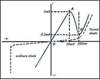 February
involved theoretical preparation and ordering the necessary parts. I started
reviving the Tesla converter on March 16, 2024. First I stretched the antenna.
Then I checked with an oscilloscope what frequency spectrum and amplitude
signal our antenna was picking up from the ether. Connect the ground point of
the oscilloscope to the water pipe. The measurement result was a big surprise.
I was expecting ether noise with a frequency of several MHz. Instead, the
oscilloscope continuously scanned in the kHz range. It rarely reached 25 MHz
and sometimes went down to the 20 kHz range. Even more surprising was the
amplitude of the signals. It was usually in the range of a few hundred mV, but
it often had peaks of 2–3 V. The signal
wavered not only in the positive range. It also went negative. This actually
caused the peak amplitude to swing by ±1–1.5
V. It was later proven that these peaks were actually noise. EMI interference signals, which are generated when large
consumers in the area, especially electric motors, are switched on. This
phenomenon will cause problems later. (The amplitude of ether noise is only 0.5
V.)
February
involved theoretical preparation and ordering the necessary parts. I started
reviving the Tesla converter on March 16, 2024. First I stretched the antenna.
Then I checked with an oscilloscope what frequency spectrum and amplitude
signal our antenna was picking up from the ether. Connect the ground point of
the oscilloscope to the water pipe. The measurement result was a big surprise.
I was expecting ether noise with a frequency of several MHz. Instead, the
oscilloscope continuously scanned in the kHz range. It rarely reached 25 MHz
and sometimes went down to the 20 kHz range. Even more surprising was the
amplitude of the signals. It was usually in the range of a few hundred mV, but
it often had peaks of 2–3 V. The signal
wavered not only in the positive range. It also went negative. This actually
caused the peak amplitude to swing by ±1–1.5
V. It was later proven that these peaks were actually noise. EMI interference signals, which are generated when large
consumers in the area, especially electric motors, are switched on. This
phenomenon will cause problems later. (The amplitude of ether noise is only 0.5
V.)
After that, disconnect the electromagnetic signals from the antenna, the signals of the tens of thousands of radio transmitters, TV transmitters, mobile phone relay stations and satellites. To do this, connect an Esaki or other tunnel diode[18] to the antenna, and connect the input of the oscilloscope to the other end.[19] Obtaining this diode will not be easy, as you will have to find intermediaries. One of them is Ukraine, who ordered a lot of tunnel diodes from Russia since the Soviet times, which they also used in radar stations. A diode with such a low threshold voltage is also needed in the trigger circuit of oscilloscopes, in order to stop even a small amplitude signal.
Its main Western producer is the American company Tektronix, which sells this diode at a high price. (With them, a single tunnel diode costs HUF 7,200 + HUF 7,900 shipping cost + 20% duty.) All tunnel diodes can be ordered most easily from the eBay web store. They ask the Ukrainians for the diode, which the Ukrainian company delivers to us. The Ukrainians send 10 diodes for HUF 2,886 + HUF 3,243 shipping fee + 20% duty. It would probably be cheaper to order directly from the Russians, but due to the current war conditions and the embargo, this is impossible. The Chinese AliExpress also distributes tunnel diodes. The interesting thing about the type they supply is that it has a negative threshold voltage, which is due to the fact that this diode has a negative internal resistance. In this way, it does not reduce, but increases the signal flowing through it. The Chinese supply 5 diodes for HUF 10,535 + HUF 2,424 shipping fee (They pay the customs duty and VAT.) The order address for the various diodes can be found in the compressed folder. Additional types can be found in the eBay webshop.[20]
The isolation of the diode in itself brought almost no change to the characteristic curve of the antenna. The EMI noise appeared on the oscilloscope even after the diode. However, the amplitude of the waves decreased by a few tenths of a Volt when silicon diodes and Schottky diodes were used. The tunnel diodes, on the other hand, stood the test of time. The Ukrainian Esaki diode barely reduced the amplitude. (The opening voltage of gallium arsenide Esaki diodes is 0.17-0.18 V.) And the oscilloscope did not show any decrease in the Chinese Esaki diode. (The reason for this is the negative internal resistance.) The true behavior of the diodes will be revealed after connecting the load circuit, the capacitor and the transformer. Switching on the capacitor resulted in a big change in itself. He lowered the antenna. The larger the capacity, the smaller the amplitude of the wave. It did not charge the capacitor. Unfortunately, none of the inventors addressed the capacity and type of capacitors. We have to figure that out.
Well, then let's connect the first transformer afterwards. But what size and what iron core? There was no mention of this either. Before we start experimenting, let's find out what transformers were like 90 years ago. An iron plate transformer alloyed with silicon was a sure thing, because the Hungarian inventors of the transformer, Miksa Déri, Ottó Titusz Bláthy and Károly Zipernowsky, had already used it and even patented it in 1885. However, they could not use Hypersyl transformer iron, because it is the XX. appeared in the second half of the century. The hypersilic iron core is also a silicon alloy. It is produced in the form of a tape, which is rolled up in an oval shape.[21] The individual layers are glued together with synthetic resin, then they are cut in half in the middle, and the sawn surfaces are polished to a mirror shine so that they fit without gaps. The advantage is that it is very easy to install. After winding the coil body the two C-shaped cores just need to be pushed in and attached to each other with a steel tape. Since this iron core form does not contain unused corners, its efficiency is 30% higher than that of the EI-shaped plated (laminated) transformer. However, its production cost is higher, which is why it could not displace the traditional transformer.
They also couldn't use ferrite iron cores. "Ferrite" is a Japanese invention born from the research of Dr. Yogoro Kato and Dr. Takeshi Takei of the Tokyo Institute of Technology in 1930. However, its production and wide application did not happen until later. Thus, it is unlikely that Tesla used a ferrite-core transformer in the converter invented in the early 1930s. Not because the magnetic conductivity of the ferrite iron core is quite low. However, in principle, a permalloy iron core could be used. Permalloy was invented in 1914 by physicist Gustav Elmen of Bell Telephone Laboratories. The approx. The transformer plate, which contains about 80% nickel and 20% iron, has a very high magnetic permeability, which makes it suitable for transforming high-frequency signals. Its main field of use is audio technology. It can also be used as magnetic shielding to block magnetic fields, although MU plate is more suitable for this because it is more malleable and easier to work with.
While the relative permeability of an ordinary iron sheet is 300-600, that of a silicon-iron transformer sheet is 6000-8000, that of a hypersilic sheet is 30,000, that of permalloy alloys is 80,000-300,000, and that of a superpermalloy sheet is 8,000,000. This means that the most suitable transformer core for us is permalloy. The only problem is that it is very expensive. However, small transformers can be obtained cheaply. Of course, it doesn't matter where we buy it. We can also order this at the cheapest price from the AliExpress online store. Cheap ferrite core transformers cannot be used in the Tesla converter. The magnetic permeability of ferrite alloys ranges from 100 to 4000. Even the magnetic permeability of high-frequency nickel-zinc or manganese-zinc ferrites is only half of the magnetic conductivity of conventional silicon-iron transformer plates. Therefore, it is not suitable for transmitting or transforming millivolt or microvolt signals. This requires an iron core with high permeability.
So its magnetic conductivity is very high, but does it work at high frequencies? Ether noise has a wide frequency spectrum. If it can only utilize the low frequency waves, then its efficiency is not very good. (Conventional silicon alloy transformer iron saturates at 150 Hz. Above that it does not work. Artificial Intelligence answered the question: „What is the saturation frequency of a permalloy transformer? A few hundred Hz, a few kHz or a few MHz?” – gave this answer: „Permalloy is very efficient at low frequencies (below 1 kHz) It handles audio signals and power frequencies comfortably. It is still extremely efficient at medium frequencies (1 kHz to 1 MHz). At high frequencies (above 1 MHz) its performance starts to decrease as we go into the megahertz (MHz) range. In summary, permalloy iron is versatile and suitable for a wide frequency range, from the lower megahertz range it can vary depending on alloy composition and other factors, but generally provides reliable magnetic properties in these frequency bands.”
All in all, we need this transformer. Now it is only necessary to determine the transformer size of each stage.[22] In the first stage, a miniature transformer must be chosen to transform the antenna's signal in the mV range. AliExpress offers us 50 pieces of 11 x 10 mm EE10-A1 high-frequency transformers for HUF 2,898 + HUF 5,464 shipping fee.[23] There is also a smaller sized transformer. The size of the EE8.3 is 9.5 × 9.5 mm. There is also an EE5.0 size, but this is already produced in chip form. These micro transformers are used to transform signals of a few mV. Since the signal amplitude of our antennas reaches 0.5 V, let's choose a slightly larger one. The next level is EI 14. (The number after EI indicates how wide the iron core is, in millimeters.) At AliExpress, 5 pieces of 14 × 12 mm EI 14 Permalloy Audio Transformer 600 : 600 Ohm cost only HUF 726 + HUF 628 shipping fee.[24] (There is also a cheaper version of this transformer, with wire legs. Do not buy this one, because the I-shaped iron plate has been spared from it. (It has an EE-shaped iron core.) Because of this, it has a lower magnetic conduction delay.) Even worse, as a result of the bending, the wire legs can twist, break, and the transformer becomes inoperable.
Use an EE 19 size permalloy transformer for the second stage. Size: 19 × 15 mm. This is also sold by AliExpress at a rather expensive price for its size. It costs HUF 5,634 + HUF 2,035 delivery fee.[25] (There is also a cheaper version in the compressed folder, but its iron core is glued together. You have to ask the manufacturer through the store to deliver it coiled as we requested.) For the third stage, the EE 25 size permalloy transformer seems to be the most suitable. Size: 25 × 20 mm.[26] Price: HUF 4910 + HUF 2184 delivery fee. After the arrival of the transformers and the construction of the first three stages, we will try to revive the Tesla converter. Don't be surprised if it doesn't work out. There are several reasons for this. The 2-3 V amplitude peak provided by the antenna drops to 0.5 V already after the first stage. The reason for this is that the low-capacity capacitors eliminate the transient waves created by EMI. This would not be a problem, because the effective voltage of 500 mV can be increased to hundreds of Volt with a 12-stage amplifier. However, for this, the valving and resonance often emphasized by Tesla and Moray would have to start.
However, there is no sign of this. The lack of valving is to be found in the characteristic curve of the tunnel diode. As shown in the figure above, the opening voltage of the Esaki diode is very low, which leads us to conclude that it is excellently suitable for almost lossless demodulation of the signal of a few hundred mV of the antenna, as well as for preventing the formation of the LC parallel oscillating circuit. However, this does not happen because the Esaki diode has no closing voltage. It also conducts the current in the reverse direction, even better than in the opening direction. Therefore, it does not prevent the formation of a parallel vibration circuit. Since the efficiency of oscillatory circuits based on transverse waves does not reach 100%, nothing of the initial signal remains at the end of the transformer chain. To prevent this, Tesla prescribed valving, i.e. the charging of the generated free energy from stage to stage.
Since he used a cold-cathode electron tube for this, he did not run into this obstacle. In contrast to semiconductor rectifier diodes, the opening direction characteristic of electron tube diodes is not exponential, but almost linear. They also have no threshold voltage. Although to a small extent, they start to open already at zero voltage. And their closing voltage can reach hundreds of V. So it was ideal for creating the converter. However, the type 70-L-7 electron tube used by Tesla is no longer available anywhere. And they don't make new ones. Electron tubes are still manufactured for audiophiles, but they are all triodes and pentodes.
You can probably find the parameter table of type 70-L-7 at well-established electron tube manufacturers, and perhaps even its technological description. Thus, there would be no obstacle to its re-production. By modernizing it, it would be well integrated into the electronic components. For this, it would have to be produced in a miniature version. Not in a form that can be fitted into a socket. It is advisable to provide it with solderable wire feet. Older people still remember that at the end of the 1950s, the first domestic pocket radio, the Terta T406, had such miniature electronic tubes, which were operated from a built-in 70 V battery. They asked for a month's payment for it, but many people bought it because the small finger-sized electron tubes produced similar sound quality to the expensive radio tuners produced for audiophiles.
In the world of semiconductors, the ideal solution would be the field electric diode that I invented. However, no one is willing to manufacture this. Forty years ago, the License Invention Sales Company offered my three semiconductor inventions to the Microelectronics Company. The CEO did not claim them. He was soon replaced. The new CEO also turned down the offer. After that, the chip manufacturing plant of Mikroelektronikai Vállalat burned down. The damage was so great that the company fell into it. Their factory producing diodes, transistors and integrated circuits in Gyöngyös was also closed. After that, domestic semiconductor production ceased for decades.
However, Infineon Kft. in Cegléd established a modern semiconductor manufacturing plant in 2018. The joint venture formed from the former semiconductor division of Siemens manufactures discrete semiconductor devices in addition to chips. I recently wrote a letter to Infineon Technologies Bipoláris Kft and offered them the production of the field-electric diode. I asked them to send me a sample that I could measure. Only the emitter layer of the 2N 1613 transistor should have been doped to the maximum in order to reduce its closing voltage. They didn't even reply to the letter. After that, I also offered this opportunity to the American Texas Instruments. They didn't reply to my letter either. We are not going anywhere with the expensive Esaki diode, idolized in the electronics industry, because the tunnel diode is not a diode. What kind of diode has no closing voltage? The Esaki diode is not a diode if it is not an oscillator. It amplifies the signal with its negative internal resistance between 50 mV and 300 mV. It alone triggers an amplifier circuit. The field electric diode does the same, but in a much wider band.
In this situation, a different solution must be chosen, a forced solution must be tried. The silicon rectifier diode is out of the question, because its threshold voltage of 0.6-0.7 V eats up the antenna signal. The Schottky diode is also not good because its opening voltage is 0.4 V. For lack of a better choice, choose the germanium diode. Its opening voltage is 0.2 V. The most suitable diode for detector radios is the gold-pin type OA1182. Unlike the Esaki diode, this has no negative internal resistance, but the field electric diode does. It would be worth producing, because its negative internal resistance creates extra current and additional free energy in the converter. It is possible that the type 70-L-7 electron tube used by Tesla also had a negative internal resistance, but no one mentioned this. And it is no longer possible to measure, because this 90-year-old electron tube, if it is found somewhere in the attic, has already disintegrated. Another advantage of the field-electric diode is that the third semiconductor layer increases its closing voltage, which can reach up to 250V. As a result, it will be applicable in all stages of the converter, i.e. it will produce additional current in each stage.
For lack of a better option, let's stick with the germanium diode for now. Replace the tunnel diodes with germanium diodes.[27] Start the converter and measure the input-output voltage of each stage with an oscilloscope. Don't be surprised if free energy production doesn't start even now. According to Tesla, the main producer of excess energy is resonance. The prerequisite for resonance is the same mass of the primary and secondary coils. The brochures state the ohmic resistance of each transformer. Seeing this, it can be determined that the length and therefore the weight of the two coils are different. Unfortunately they have to be rewound. Fortunately, the plates of the iron core are not glued together with synthetic resin, so they can be easily disassembled. Only the insulating tape holding the plates E and I together needs to be removed.
The coil body can also be wound using an automatic winding machine, but this is very expensive. The delivered machine is difficult to assemble and it takes a long time to learn how to use it.[28] For development purposes, the manual winding device is also suitable. We can use this immediately upon arrival. The price is also bearable. It costs HUF 22,600 including delivery in the AliExpress online store.[29] Screw it to a thick board so that it does not slip during use. However, when winding large transformers, the board will also move. This can be prevented with a vacuum base screwed into the four corners of the board. In the AliExpress online store, you can find vacuum suction pads of various sizes. Enter the term rubber suction cup in the search bar. We get a lot of hits on it. Adjust the diameter and length of the screw to the thickness and weight of the board. (A smooth, lacquered table surface is required to use the vacuum base.)
There are two ways to wind the primary and secondary coils with the same mass. Parallel winding is the safest. The first transformer is wound from hair-thin enameled copper wire, i.e. Ø 0.06 mm. Let's order two 300 gram spools of it. Hide a metal or wooden rod in the two plastic spools and place it in your lap. We hold the two strands together and wind them parallel to the coil. (This is also beneficial because the double strand is less prone to tearing.) Before that, however, sand off the enamel from the ends with polishing paper, cover them with tin, and solder them to the legs on one side of the transformer stand.[30]
Tie the thin wire to the base of the legs protruding from the vinyl stand. Clean it, then cover it with tin for approx. 1 cm long. Afterwards, we screw this section to the base of the legs with pointed tweezers, and then weld it on. Guide the end of the wire through the slots of the stand to the legs so that it is not damaged. Wrap the coil full and solder the ends of the wires to the legs on the other side of the stand. First, use an ohmmeter to measure which ends belong to the beginnings. The winding direction doesn't matter either. If the beginnings and ends are reversed, a bifilar winding is created. This low-induction winding has the consequence that the magnetic fields of the two windings degrade each other. Therefore, we solder the beginning of the two coils to one side of the stand and the end to the other side. Thus, only the coil ends need to be identified with an ohmmeter. Solder in so that the beginning and end of the primary and secondary windings are opposite each other. Since we have done parallel winding here, the primary and secondary windings are interchangeable. However, if the voltage is to be transformed up or down, it must be noted where the primary and secondary windings are located. Avoid transformers with nylon scaffolding. If possible, order vinyl scaffolding, because it does not melt during soldering. In addition, the hard vinyl holds the transformer firmly and does not shake off the printed circuit board even when installed in a car.
You will need an accurate scale for winding. For this purpose, it is advisable to buy a kitchen digital scale with a measurement limit of 500 grams. With this, we can also measure spices and baby food with the help of a small plastic bowl. We can also get it from China at the cheapest price. The Kitchen Digital Scale Mini Pocket Scale costs HUF 3,900 including shipping costs.[31] Accuracy: 0.01 gram. Works with 2 thin pencil batteries (AAA) or USB charger. (Include alkaline batteries, because carbon-zinc batteries discharge after half a year and release acid. This destroys the connectors of the battery holder. Although the alkaline battery is more expensive, it can be used for 4 years.) With dual power supply, we can avoid the inconvenience of batteries run out when the scale is most needed. If we work with previously purchased unmarked enameled copper wire, or if we extract winding wire from a transformer of a disassembled device, we will also need a micrometer to determine the wire diameter. The possible way to get it is also in the compressed folder.[32]
Its opening voltage is 0.34 V, its closing voltage is 200 V, and its maximum current is 5 A. A 30A10 diode may be needed in the final stage. Its maximum current is 30 A, and its maximum closing voltage is 1000 V. Since the opening voltage depends on the closing voltage, its threshold voltage is 0.48 V. However, the threshold voltage of the low closing voltage 45 V type 30SQ45 Schottky diode is only 0.14 V. Its maximum current is 30 A.
The Schottky diode is an invention of the German physicist Walter H. Schottky. It is characterized by the fact that it contains only one semiconductor layer. Therefore, in contrast to double-layer silicon diodes, its threshold voltage is also half, max. 0.4 V. Since it contains only one n-type semiconductor layer, its switching speed is also higher. For this reason, today only this is used as a rectifier diode in switching-mode power supplies. This is not hindered by its price either, because it costs the same as double-layer silicon rectifier diodes, i.e. it is very cheap. The rectifying effect of the metal-semiconductor layer is unclear. It cannot be ruled out that the ether plays a major role in this phenomenon. However, physicists deny this because, as we know, there is no ether. Its voltage in the closing direction usually does not exceed 250 V. This does not cause us any particular problems, because we do not have to use diodes corresponding to the maximum output voltage in each stage. The diode only has to withstand the voltage occurring in each stage. (Measure the voltage of the previous and next stage. The voltage acting on the diode will be the difference between the two.) Do not use an unreasonably high voltage version, because the lower the closing voltage, the lower the threshold voltage.
The fourth transformer should be EI 35 in size. You can order it from the eBay web store.[33] Price: HUF 28,832 + HUF 4,187 delivery fee + 20% Customs.[34] Since this transformer is not wound, we get the E plates in a separate bag and the I plates separately. When assembling, do not put them in a package under the E plates, as this will cause the iron core to slide apart. The iron cores with EI plates must be assembled in such a way that the E plates are inserted alternately from top to bottom into the coil. As we inserted an E plate, place the I-shaped plate next to it. In this way, the iron core will not fall apart and its magnetic conductivity will be maximum. (If it slips out of it, after inserting the E plates, push the I plates into the gaps. If necessary, make room for it with a thin-bladed knife, e.g. wallpaper cutter. It may happen that the last one has to be gently tapped with a hammer. Do not miss a plate, because this will damage the magnetic conductivity of the transformer. It doesn't hurt to have a pair of flat pliers nearby.)
The assembly of the transformers did not end there. We do not yet know what effect the mass use of the Tesla converter has on our environment. Will there be EMF[35] or EMI[36] radiation. Tesla prevented the formation of electromagnetic resonance by moving the demodulator diode, but what effect does this have on electrosmog? There will still be resonance in the converter, but it is created by longitudinal waves. We don't know if and how to defend against it. Developers are currently protecting themselves against radio frequency radiation with copper foil insulation.
After the transformer has been assembled, a pure copper plate with a small soldering tab at the end is pushed in behind the last lamella, next to the central extension of the iron core. The iron core of the transformer is grounded through this soldering lug. However, this does not prevent the electromagnetic radiation of the coil. This can be done with thin copper foil. The coil body is wrapped in at least one layer across its entire width with copper foil, and this is also soldered to the ground point. The problem with this solution is that the Mylar tape protecting the coil and the copper foil take up a significant amount of space on the coil body. Therefore, less copper wire can be wound on it. That's why many people perform the shielding by wrapping the winding body together with the two extreme sides of the iron core, i.e. they almost wrap the transformer.
You can get copper foil at the cheapest price in the AliExpress online store. Enter the term adhesive copper tape in the search bar, and you can choose from a large number of adhesive and non-adhesive tapes, in different thicknesses and widths. (If necessary, the earth point of the transformers must be connected to the water pipe.) Eliminating magnetic radiation can be a bigger problem. Longitudinal waves cause very strong magnetic radiation. They currently protect against this by placing the entire transformer in a case pressed from MU plate. The bottom is also sealed with a plate that only has an opening big enough to fit the connecting wires. However, the MU plate with high magnetic conductivity is very expensive. Enclosing all the transformers in such a case would cost a lot. If shielding is unavoidable, the entire converter must be placed in a box made of MU sheet, which would be covered by a designed outer plastic box.
It is no small problem that we cannot measure the etheric magnetic radiation. It doesn't have any instruments. The only way to sense it is with a compass. Get a large semi-precious stone rotating needle bearing compass and approach the transformers with it. Let's try the military version that can be ordered from the AliExpress online store.[37] Price: HUF 1,043 + HUF 747 delivery fee. (If the web address does not start, copy it into the address bar of the browser.) A professional design[38] with rotating agate stone, with needle bearings, is also available, but it is quite expensive. Price: HUF 24,154 + HUF 3,000 delivery fee. It would be worth trying Dr. György Egely's vitality meter as well. Website: https://egely.hu/vitalitasmero/ You can also order by clicking on the Product link.
However, we are not there yet. After installing the wound fourth transformer in the device[39], the question arises: how to proceed? Even this EI 35 permalloy transformer cost quite a lot, and as the size increases, the prices increase sharply. The next size would be EI 48, EI 66, EI 96, EI 120, EI 150, EI 171 and EI 192. However, such large pemalloy transformers are not distributed by online stores, because they would be so expensive that they would not be able to sell them. South Korean EI 48 nickel permalloy iron core with single-chamber body only available on eBay.[40] Price HUF 38,321 + delivery fee + 20% Customs. However, for this money, we get 2 pieces. The largest size we can order here is the EI-57 single-chamber body.[41] Price HUF 51,825 + delivery fee + 20% Customs. In this case, 2 pieces will be sent. However, the iron cores are packed together. Divide them exactly in half. A digital scale is best suited for this.
Inquiring about other sizes, eBay allows us to send a letter to the manufacturer. (I tried this too, without success. They didn't answer my letter either. However, I found the Korean manufacturer on the Internet. These transformers can be ordered much cheaper from Hankook Core Co., Ltd. They sell the EI 48 nickel permalloy iron core for HUF 20,516. The other iron cores are probably cheaper than them. Click Contact Now to contact them.)
If we manage to get to serial production, we won't have these problems anymore. Large users are supplied with transformer cores by plants with a huge production base. However, they do not serve individual inquirers. Goods must be ordered by the ton from them. The smallest quantity that can be ordered is 20 pieces per type. Among the world's transformer manufacturing companies, the Chinese ones are also the cheapest. One of them is Evergrowing Resources Cooperation Limited in Nanjing. They produce coiled iron core, in several versions. These easy-to-install iron cores are wound from metal tape glued together with synthetic resin. Then it is cut in half in the middle and the sawn surfaces are polished to a mirror shine.
Their favored type is the nanocrystalline iron core.[42] Nanocrystalline materials are a new generation of advanced soft magnetic alloys used to control and transform electrical current. The addition of niobium and sudden cooling of the hot-rolled iron plate means they have crystal sizes below 10 nanometers, resulting in high permeability, low loss and high inductance over a wide range of environmental and mechanical conditions. (The hot iron plate is cooled at a rate of approx. 1 million °C/sec.) No numerical data is provided for its magnetic conductivity. They only write that their amorphous iron core has "high permeability, saturation induction, electrical resistance and low core loss". Then they add that it "can replace silicon steel, permalloy and ferrite materials".
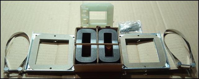 The
extent to which permalloy can replace the iron core can only be determined by
trial. However, there is no doubt that this type of iron core is very cheap.
Price: US$ 0.10-13.40 / pc. This means
that even their largest, 171 mm wide iron core costs only HUF 4,700.[43]
A coil body is not manufactured for it, but C-shaped coil bodies are easily
available from specialized manufacturers. Make sure that you do not order a
single coil body, but a double iron core. Insert one U-shaped iron core on the
right and left side, and two U-shaped iron cores on the top and bottom. As
shown in the picture with hypersyl transforms. This makes the transformer more
expensive, but its efficiency doubles.
The
extent to which permalloy can replace the iron core can only be determined by
trial. However, there is no doubt that this type of iron core is very cheap.
Price: US$ 0.10-13.40 / pc. This means
that even their largest, 171 mm wide iron core costs only HUF 4,700.[43]
A coil body is not manufactured for it, but C-shaped coil bodies are easily
available from specialized manufacturers. Make sure that you do not order a
single coil body, but a double iron core. Insert one U-shaped iron core on the
right and left side, and two U-shaped iron cores on the top and bottom. As
shown in the picture with hypersyl transforms. This makes the transformer more
expensive, but its efficiency doubles.
In the case of larger transformers, care must be taken to secure it. If you don't want to use induction-reducing steel clamps, clamp the two U-shaped cores together with Mylar tape, then apply a drop of epoxy resin to the side of the meeting surface of the two iron cores, both in front and back. (The epoxy resin sold by Aliexpress is of very good quality. It dries to rock hard in a short time, and you can't snap it off even with a chisel.) Always lay it on the base plate and fasten it so that it is as little affected by vibrations as possible. We will not find a thick vinyl stand for this. This must be done by an industrial designer. For us, the iron core made from MU plate is the most suitable.[44] It's not expensive either. Over 100 pieces only US$ 8.50 each. It is also worth trying their transformer core made of neodymium alloy glass plate.[45] Fortunately, you can order 1 piece of each variety from them to try. So it's not cheap, $10/piece.
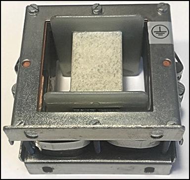 Unfortunately,
I didn't have the opportunity to try their iron cores, because they didn't
reply to my letter either. I didn't leave it at that. I tried again later, but
now with chat. It wasn't easy either, because you had to wait hours for the
answer. First, I asked whether the magnetic conductivity of the MU plate, glass
plate, nanocrystalline or amorphous iron core is closest to that of the
permalloy iron core. I received a surprising answer: "We only have
amorphous and nanocrystalline materials". I do not understand. So why is
the MU plate and glass plate iron core listed on their website? Second, I
asked which of the two recommended types is high-frequency, which has better
permeability. The answer was one word: Amorphous. Well, then you will have to
try this and compare its effectiveness with
the South Korean permalloy plate iron cores. It is also advisable to do
this because the Chinese coiled iron core is an
order of magnitude cheaper and easier to assemble. Assembling the
plate iron core is quite labor intensive.
Unfortunately,
I didn't have the opportunity to try their iron cores, because they didn't
reply to my letter either. I didn't leave it at that. I tried again later, but
now with chat. It wasn't easy either, because you had to wait hours for the
answer. First, I asked whether the magnetic conductivity of the MU plate, glass
plate, nanocrystalline or amorphous iron core is closest to that of the
permalloy iron core. I received a surprising answer: "We only have
amorphous and nanocrystalline materials". I do not understand. So why is
the MU plate and glass plate iron core listed on their website? Second, I
asked which of the two recommended types is high-frequency, which has better
permeability. The answer was one word: Amorphous. Well, then you will have to
try this and compare its effectiveness with
the South Korean permalloy plate iron cores. It is also advisable to do
this because the Chinese coiled iron core is an
order of magnitude cheaper and easier to assemble. Assembling the
plate iron core is quite labor intensive.
Even before ordering a larger batch, it would be worthwhile to test which type of transformer is more efficient, the one with the plate or the coiled iron core. Let's compare the EI-57 transformer that can be ordered on eBay with a MU plate transformer of similar size and weight.[46] If you are interested in other suppliers, take a look around in the alibaba.com online store. Enter permalloy transformer core in the search bar. There are many transformer manufacturers here.
Don't rush the purchase of large transformers, because we are still having trouble reviving the first three stages. No matter what we do with it, neither the valving nor the resonance wants to start in the transformers. No wonder, since there are no capacitors in it. Determining their value is not difficult. The theoretical solution is to measure the inductance of the coil with the special multimeter (LCR Tester) we purchased earlier. Based on this, we use the Thomson formula to calculate how much capacity is needed to achieve resonance.[47] However, theory does not always translate into practice. The Thomson formula cannot accurately take losses into account because it does not know the goodness factor (Q value) of the components. The resulting capacity value is only informative.
The perfect solution is measurement. Let's revive our school studies, then highlight the individual stages, and by measuring the current flowing through them, determine at what capacitance value they resonate. Then we measure the capacity of the capacitor, because due to aging, drying and the tolerance limit, it may not have the same value as what is written on it. In high school, our physics teacher drew on the blackboard the parallel LC vibrating circuit and a lamp connected in series with the capacitor and the coil. Then he connected a lamp in series with the power supply. Powered by alternating current, the lamps glowed at different intensities. If the lamp connected in series with the supply current also lights up, it clearly indicates that there is no resonance. If the lamp connected in series with the capacitor glows brighter, it indicates that the capacity is too large. In the case of a capacitor with a small capacity, the inductance conducts the current better, and its lamp lights up more brightly.
This simple circuit is used as an oscillator. If two LC vibrating circuits are placed next to each other and the coils are placed on a common iron core, a coupled vibration is created. Inductive coupling occurs in transformers. In this case, the magnetic field occurring in the primary coil creates a eddy electric field in the secondary coil. The energy transfer between the two vibrating circuits is most perfect if the natural frequency of the two vibrating circuits is the same, that is, L1 × C1 = L2 × C2.
The condenser decade cabinet is most suitable for determining the capacity of the capacitor. However, this is very expensive. Therefore, let's approximate the required value by trial and error. Since we will not find a capacitor with an ideal value, set the exact value by connecting a capacitor with a larger and a smaller capacity in parallel. Then the lamp connected in series with the supply current goes out, which indicates that resonance has occurred. Ohmic current does not flow because the capacitance and inductance of the vibrating circuit feed each other. The reason for this is that the capacitor accelerates it by 90° and the inductive coil delays it by 90°. This 180° phase shift makes the supply current unnecessary, because while the current flows upwards in one branch, it flows downwards in the other branch. The energy therefore goes round and round in the parallel vibration circle. (Unfortunately, in reality, the situation is not so ideal, because due to the losses of the coil and the capacitor, as well as the ohmic resistance of the connecting wires, a small amount of supply current is needed. Without this, the vibration would subside and then cease.)
We try to put what we learned at school into practice. It will not be easy. The first difficulty is that the antenna's weak signal cannot light even the smallest LED. Therefore, they must be replaced with a current meter. If we have three current meters, we are in an easier situation. If there isn't, we have to measure in the individual branches in turn. Do not bother with the antenna circuit of the first stage, because the current strength of the signal provided by the wire antenna is so low that it is almost immeasurable. Here, the criterion for selecting the capacitor should be keeping the widest frequency spectrum. The signal of the antenna is already attenuated by a low-capacity capacitor. A 100 nF capacitor completely cancels the antenna signal. A few pF capacitors are needed here.
The exact amount can be determined with an air variable capacitor. (There are several recommended types in the compressed folder. It is worth choosing the type with a gear ratio, because we will need its fine controllability and stable value in the development of the Tesla generator. Let's try to get it, because radios with rotary capacitors are no longer manufactured. In modern radio tuners, the tuning is solved with a capacitive diode. A rotary capacitor can only be obtained in second-hand markets, in limited quantities.)
Determining the maximum and minimum of the frequency spectrum will not be easy, because after pressing the MEASURE button, the frequency values on the oscilloscope change so quickly that it is impossible to follow with the eye. (It would be a good solution to make a video recording of the screen and play it back in slow motion. The cheap camcorder.4k.ultra.hd camera is also capable of this.) However, we can already start experimenting with the secondary side of the EI 14 transformer. Due to the high magnetic conductivity of the permalloy iron core, the signal of the antenna appears almost entirely on the secondary coil. The loss is only 15%. (A peak-to-peak amplitude of 3 V becomes 2,5 V.) Because of the galvanic isolation, whatever we do here, it will not affect the antenna circuit.
Take our RLC meter and measure the inductance of the secondary winding of Tr1. It largely depends on how many turns we wound on the transformer and how tightly, but it will be at least 150 mH. For this, let's try to find a capacitor with a capacity that starts the resonance. No matter how hard we try, it won't work. And even less so for the second and third degrees. The reason is very simple. Resonance requires current that can circulate in the coils. The effective value of the 3 V peak voltage of the antenna is only 1.5 V. And this small voltage is eaten up by the copper and iron losses of the transformers and the dielectric loss of the capacitors.
It is no coincidence that so far no one has succeeded in reconstructing the Tesla converter, even though thousands of engineers and technicians have tried to do it in the last 90 years. They all gave up. The scientists didn't even start because they think the Tesla converter never existed, the story about it is an urban legend. There is no question of arrogance. It's not a legend because Tesla's quietly running electric car was seen by hundreds of people on the streets of Buffalo. The show lasted for a week, and during that time he also took passengers on a test drive. Journalists also made a national sensation out of the electric car. And there can be no question of arrogance, because Tesla did not need such dubious popularity.
He invented the alternating current generator, the method of three-phase, high-voltage power transmission. The losses of Edison's direct current system were so great that a power plant had to be set up in every district. Without Tesla's invention, there would be no electrical or electronic industry. We would still be in medieval conditions. Electricity would only be available in big cities, at a high price. Tesla can't be accused of keeping an important fact quiet, like other profit-seeking inventors, he took his secret to the grave with him. The reason for the failure is that it is not possible to reconstruct this device with our currently used, so-called modern components.
Current and voltage are needed to start valve actuation and resonance. However, this gradually disappears. The loss of the first stage is still negligible, because only 0.5 V of the peak-to-peak 3 V antenna signal disappears due to the copper and iron losses of the transformer. After that, however, the loss will be radical. The loss in the second stage is already 1.5 V, while only 0.5 V reaches the output of the third stage. This is not only due to the relatively high threshold voltage of the germanium diode and the copper and iron losses of the transformers.
A more drastic reason is casting. Add to that the shunting of the diode. Every semiconductor element has a return current, which can also be understood as having an internal resistance. This is quite large, but its effect is no longer negligible at low voltages and low currents. In this circuit, its effect is so great that it paralyzes the converter. We can't defend against this even with up-transformation. If we take off the secondary winding of the transformers and wind many more turns of much thinner copper wire on it for the same weight, we will not get anywhere either. The voltage in the secondary coil increases, but the current, i.e. the load capacity, decreases. For this reason, the shunting effect of the diode applies in the same way.
More precisely, it is not the diode that drains the secondary coil of the previous transformer, but the primary coil of the following stage. An ideal valve diode could prevent this, but semiconductor diodes cannot valve. In the closing direction, they act as resistance and thereby shunt. This can be easily confirmed by replacing the diodes with capacitors. The capacitor does not conduct direct current, so it does not shunt backwards. The leakage current of high-quality polypropylene film capacitors is minimal. If a 100 nF capacitor is soldered in place of the diodes, the shunting is eliminated. Due to the high magnetic conductivity of the permalloy transformers, the 3 V amplitude of the antenna appears almost without loss on the secondary winding of the third transformer. But what are we going to do with it? The series capacitor prevents the formation of a parallel vibration circuit, so resonance does not occur between the coils. We can't expect any additional amplification either, since the capacitor has no negative internal resistance.
This phenomenon did not occur with Tesla because he used an electron tube. In the electron tube, there is nothing between the cathode and the anode. Not even air, as the glass tube is sealed in an airtight space. Therefore, cold-cathode electron tube diodes have no reverse current. Therefore, the individual grades are not reduced. The copper and iron losses of the coils, as well as the losses due to the leakage current of the capacitors, were eliminated by the amplifying effect resulting from the negative characteristic of the electron tube. For this reason, we will never revive the Tesla converter with semiconductor diodes. This requires an electron tube. But only in the first three stages. According to his assistant, Tesla also used type 70-L-7 electron tubes only in the first three stages. In the subsequent high-current and high-voltage stages, ordinary electron tube diodes were used. These probably had no negative internal resistance.
This does not mean that there is no need for a field electric diode. Its negative internal resistance characteristic, which prevails in a wide voltage range, produces additional current in the further stages, which further improves the efficiency of the converter. And its small leakage current no longer affects the high-performance stages. And in the Tesla converter that can be installed in thin smartphones, this diode will be needed in every stage, because in the absence of other options, it produces the free energy.
We have one more option left to revive the Tesla converter, pre-magnetization. Tesla already found that the signal of the antenna is so weak that it cannot magnetize the iron cores. This requires external intervention. An external current must be connected to the antenna input, which is capable of starting the excitation in the transformers. For this purpose, he pushed two magnetic bars into an electromagnet, while Moray stroked an electromagnet disguised with insulating tape with a permanent magnet. This method is no longer applicable, because no one will get out of their car and open the engine compartment with a piece of magnet to make the current source work. The push-button method must be used. There are two ways to do this. For one, I carefully wrapped a 65 mm diameter, 20 mm thick Mn-Zn ferrite ring with thin enameled copper wire. Then I inserted an 8 mm diameter neodymium supermagnet into the center of the toroidal electromagnet. Pulling the magnetic bar up and down, I could not induce a voltage higher than 0.5 V with it. Well, that's very little.
The other method is to move the electromagnet. I wound a very thick thin copper wire on a ferrite rod and pulled this spindle-shaped electromagnet in a 45 mm diameter, 8 mm thick neodymium alloy ferrite magnet ring. I ordered this magnet ring used in speakers because I thought the neodymium alloy made it strong enough. I was very disappointed. After it arrived, it turned out that its magnetic radiation does not even reach half the field strength of a neodymium permanent magnet. Wrapped up, he behaved accordingly. The most that could be extracted from it was a few hundred mV. I also tried the iron-neodymium alloy magnet ring. It was not possible to get more than 1 V out of this either. This is also very little.
I looked around the AliExpress online store and discovered a mini dynamo. The 0.1-24V DC Generator Set cost only HUF 1,440.[48] After it arrived, it worked as I expected. By spinning it with my fingers, 8 V came out of it. Well, this will be enough to magnetize the transformers. I was wrong. Nothing happened in the first three stages of the converter. The 8 V pulse went through the transformers and appeared at the output. In order to increase the speed, I attached a thin, notched knob to the shaft of the dynamo. That didn't help either. The situation remained the same. This is understandable. The pre-magnetization of the transformers can also be caused by the 3 V transient spikes of the antenna. No help needed. Excitation is inhibited by semiconductor diodes.
Our modern age will also hinder the use of the Tesla converter. This is due to electrosmog. Inductive consumers (electric motors, arc welding transformers, X-ray machines, etc.) emit such strong EMI radiation that it increases the amplitude of ether noise six times. Of the 3 V peak-to-peak amplitude detected by our antenna, only 0.5 V is ether noise. This is a big problem, because what are we going to do with the Tesla converter in places where there are no sources of interference. In Mongolia, e.g. there is very little satellite coverage and there are no cell phone relay stations close to each other. This is also the case in the Sahara. Therefore, the Bedouins would not be able to prepare their food on their stoves heated by a Tesla converter. Even the inhabitants of the Brazilian primeval forests would not go far with the Tesla converter designed for transient pulses. Many people could say that they don't need it. There is, though. They also want to listen to the radio, watch TV, and surf the Internet. An even bigger problem is the fact that many airplanes fly over the primeval forests of Brazil. If these are later converted to electric drive, they will fall into the trees due to the signal reduction. The lack of electrosmog can also be a problem in America. In this country, cities are hundreds of kilometers apart. In the meantime, there may be no coverage on the way. If an electric car stops on the highway because of this, it can cause a mass accident.
Therefore, it seems like an obvious solution to design the device for 0.5 V ether noise. In this case, what happens if the car reaches the city, where the Tesla converter receives a signal six times as large. This causes the output voltage to increase significantly, which burns the car's engine. This can only be prevented by voltage stabilization. A stabilizer can be made for an output power of 5 or 10 kW, but it will not be cheap. In order to avoid all these problems, it would be advisable to stop using ether noise. Like nature, we have destroyed this too, so a more stable signal source must be sought.[49]
The Noise waveform of the signal generators is generated voluntarily. However, this turned out to be unusable during the development of Resonant Excitation. While the light bulb shone at full brightness with the square wave, it barely flickered when switched to the Noise wave. The reason for this is that not only the frequency of the noise wave created by the developers is constantly changing, but also its amplitude. As a result, ether free electron generation, which enables the size reduction of switching power supplies, cannot prevail. The high-amplitude pulse is followed by a small-amplitude one, which excites the transformer. It enables the rearrangement of the generated free electrons.
This requires a wave whose only frequency changes and whose amplitude is constant. There is also such a generator. It is no longer a surprise that this is also distributed by AliExpress. Let's order the DIY White Noise Generator and see what it can do.[50] Its price is only HUF 740, including shipping costs. A small problem is that they are delivered in kit form, so we have to mount the parts on the panel. (For those with a DIY background, this will not be a problem.) Requires 12 V DC. This will later be fed back from the output voltage, by inserting a small voltage stabilizer. Now switch to external power supply. It has two outputs. Connect headphones with today's standard 100 Ω internal resistance to the Jack plug output. This will not be easy, because the Jack sleeve is mono and our headphones are stereo. Therefore, pull it out a little and then push the Jack plug in. Meanwhile, sometimes the left and sometimes the right earpiece are playing. First, turn the volume control trimmer potentiometer to maximum.
If we did everything right, we will hear a pleasant, sleepy ether noise. (The distributor recommends this circuit against insomnia.)[51] It also has a high internal resistance output. We need this because the low-impedance grounded collector output would sink the tiny transformers. Do not insert the two terminals into the panel. At such low signal levels, all connecting wires must be soldered. In the case of screw connections, loosening of the screws or corrosion of the wire end can cause the device to malfunction. The output signal amplitude is 1 V at both outputs, which means that the three transformers are still needed. Now it is necessary to determine how wide the frequency spectrum of the noise generator is.
Connect the oscilloscope to the high internal resistance output. (Do not leave the headphones plugged in, because the cord acts as an antenna, which excites the generator.) The result is as described in the brochure. The amplitude of the output signal is 2 V from peak to peak, the effective value of which corresponds to the promised 1 V. (If it is less than this, measure the capacity of capacitor C1. If it is much less than 100 nF, replace it with a film capacitor.)[52] The waveforms here are nice and regular, there are no transient spikes. Also, sometimes one of them flashes, but if the connecting cables are replaced with a shielded cable, this will disappear. Its frequency response is also similar to antenna excitation. It mostly scans in the kHz band. It doesn't go into the MHz range, and rarely dips into the 100 Hz range either. Another great advantage of noise generator control is that you don't have to mount two antennas on top of the car, and you don't have to wire the room under the ceiling at home. It is no small relief that there is no need for a ground wire either.
Despite all this, the situation has not changed. The noise generator converter behaves in the same way as the antenna. In fact, worse. The output voltage was 500 mV after the first three stages of the 3 V peak-to-peak amplitude antenna converter. Now 150 mV. The loss of iron, the loss of copper, the leaking price of capacitors, but above all the return current of diodes have their effect here as well. For this reason, there is no question of valving or resonance. This version can only be revived with an electron tube. Until then, however, let's try to strengthen the excitation signal. Preamplifiers are best suited for this purpose. Countless online stores offer microphone preamplifiers. These condenser microphones amplify the μV signal by a thousand times.
First, I tried the German-made Kemo M040 mono amplifier module. I was afraid that this 2 V voltage would overdrive the input of the μV amplifier and destroy it. He survived. The noise generator amplified its 2V peak-to-peak signal to 10V. However, it pushed its frequency spectrum down to the 100 Hz range, even though, according to the brochure, the maximum transmission frequency of this preamplifier is 100 kHz. I connected the increased signal to the transformers. Only 1.5 V appeared at the output of the third transformer. Every attempt ends up in the same place. Casting does not allow the converter to come to life.
The Kemo mono preamp is not cheap. That's why I looked around the AliExpress online store. I also found two cheap preamps. I ordered but did not use them because they require a dual power supply. It's hard to find and expensive. The two 1000 W amplifiers I bought earlier have an auxiliary voltage of ±15 V, specifically for the pre-amplifiers, but they must be powered by at least a 1500 W power supply. Added to this is the current consumption of the noise generator, and these together consume the output current of the converter. I also had three 60 W amps, but they broke. They had neither input surge protection nor output short circuit protection, so they were very vulnerable. However, I have a cheap 100 W amp that was so durable that nothing broke it. In addition, it requires a single power supply, so it can be powered from the same stabilizer as the noise generator.
Well, let's see how much amplification this is. He's drunk. The amplitude of the setpoint signal is 22 V. It is strongly excited during operation. Because of this, it produces peak-to-peak amplitudes of 40 V. Since they are evenly distributed in the wave and their amplitude is roughly the same, they may not interfere with the operation of the converter. Excitement can also be perceived as noise. And the power consumption is reassuring. The amplifier and the noise generator consume only 30 mA at 12 V. This will certainly not burden the hoped-for 5 kW output. I connected this 40 V signal to the input of the converter. It wasn't ruined. The output signal of the third stage became 20 V peak to peak. It has a transient spike here and there, but that's because I didn't shield the signal lines. Well, let's see what can be done with this high-voltage version. Nothing. The diodes lower the individual stages in the same way as with the low-voltage antenna version. The beacons are working though. After connecting to the converter, the current consumption of the noise generator and the amplifier increased to 55 mA, which corresponds to a consumption of 0.6 W.
Another failure. Since they haven't solved the problem, let's forget about the noise generator and the preamplifier. Let's go back to the basic version and try to increase the secondary voltage of the transformers by resonance. This was very easy. I set the function generator to a square wave and 20 V amplitude and used the frequency control knob to find the resonant frequency of each transformer. I got varying results depending on how they were rolled. It is a common experience that the smaller the transformer, the higher its resonance frequency. I wound the third EI 25 permalloy transformer with Ø 0.15 mm enameled copper wire in parallel. For this reason, voltage transformation was hardly created. Its resonance frequency became 450 kHz. However, its load capacity was not bad. I have already tried up-transforming the EI 35 permalloy transformer. For this, I made the primary coil from Ø 0.5 mm wire. I used Ø 0.3 mm wire for the secondary coil. In this case, the secondary voltage rose to 230 V at a resonance frequency of 250 kHz. However, its load capacity has ceased.
For comparison, I wound the other specimen sent by the manufacturer in parallel from Ø 0.3 mm wire. No transformation took place here either, only the resonance frequency went up to 500 kHz. However, its load capacity has improved a lot. By connecting a 100 Ω resistor, the 22 V output voltage did not disappear, but only decreased to 0.5 V. This decrease seems to be a lot, but the output of the function generator is not stabilized, so when loaded with 100 Ω, the 20 V amplitude drops to 14 V.
I took a big step with the C 55 hypersilic transformer manufactured by the German Vakuumschmelze. I made the primary winding of Ø 0.9 mm, while the secondary winding of Ø 0.2 mm wire. Because of the thick wire, its resonance frequency dropped to 100 Hz, but its secondary voltage rose to 1200 V.[53] Its load capacity has also ceased. I already had the opportunity to compare the 65 mm wide transformers. I used Ø 0.6 mm wire for the primary coil and Ø 0.2 mm wire for the secondary coil. For the C 65 hypersilic iron core, the secondary voltage was 520 V at a resonance frequency of 28 kHz. With an EI 65 silicon alloy iron core, the efficiency is reduced to 70%. It is no coincidence that this cheap transformer iron is now only used for mains transformers.) The permeability of permalloy, MU plate and Amorphus iron cores, on the other hand, far exceeds the magnetic conductivity of the hypersilic transformer. They are also not expensive when bought in bulk.
The Chinese-made EE65B High Frequency Transformer Ferrite Magnetic Core transformer was a big surprise.[54] According to the literature, the magnetic conductivity of ferrite transformers is very low. Therefore, they are used for low-frequency use and interference filtering. However, there is also a high-frequency version, which is made with a manganese-zinc alloy. These have the same permeability as wound iron core hypersilic transformers, but are much cheaper. (The voltage and resonance frequency of the secondary was the same as that of the hypersyl iron core.) The price, including the vinyl coil body and shipping costs, is HUF 7,234. In the case of wholesale orders, this price is reduced to a fraction.[55] We can also get a free sample from Anhui Shirui Electronic Technology Co. Ltd, which operates in Shanghai.[56] If you order 1000 pieces, only $0.75 per piece or pair of 65mm wide transformer cores. They also manufacture a tube body for it. When assembling, make sure that the two E-cores must be tightly closed, and then fix their joint surface with a drop of epoxy resin both at the front and at the back. Otherwise, they hum and play music at lower frequencies. Resonance results in a serious power increase for all transformers. The secondary voltage of the transformer doubles or triples.
Resonance is therefore already present, but the transformers cannot transmit the excess voltage generated in this way to each other. Both galvanic and diode coupling reduce each other. According to Tesla, the main role of the diode is valving, i.e. charging energy from one stage to another. Another role is to prevent an electromagnetic vibration circuit from forming between the individual stages. Its third role is to prevent the ohmic effect of the coils on each other. As we have seen, the latter cannot fulfill its role due to its return current. The return current can also be understood as resistance, which reduces the secondary coil of the previous stage in the case of a galvanic connection. Let's eliminate the galvanic connection between the two stages. This can be achieved most easily with a capacitor connected in series with the diode. In the previous sections, we have already seen what happens when capacitors are installed in the converter instead of diodes. In this way, the transformers were connected in series. (This is also progress, because as a result, the primary winding of the next stage with a high input resistance does not reduce the secondary winding of the previous stage with a high output resistance. However, valve does not occur, because of this the voltage connected to the primary winding of the first stage appears on the secondary winding of the third transformer. because permalloy transformers also have some losses.)
Another problem is that each transformer has a different resonance frequency. For this reason, a transistor and integrated circuit quadrature generator should be installed in front of each of them. However, 40 A will circulate to the last stage. 40 A transistors are not manufactured. If you could get it, it would be very expensive. You could try a thyristor, but with such a large current, even this would require a palm-sized heatsink and a large fan to cool it. It is not economical to install 12 square generators in the converter. These transformers should feed each other. The prerequisite for this would be the valving, but this does not work now either.
As a last resort, put the diodes back in front of the series capacitors. Now, in principle, valving and even the tuning of individual transformers to the resonance frequency could be created. (This can be achieved with capacitors connected in parallel with the secondary windings.) However, this made the situation even worse. The diodes cut off the positive range of the square wave and carried only the negative. Not completely either. Damping effects remained despite the series capacitors. As a result, only 50 mV of the 20 V amplitude of the function generator remained on the secondary side of the fourth transformer. The resonance frequency could not be induced either. I scanned the frequency range from 100 Hz to 15 MHz and the four cascaded transformers had no resonant frequency. Following Tesla's wiring diagram above, I tried to set the resonance frequency of each transformer with capacitors connected in parallel with their secondary windings. That didn't work either. Even low-capacity capacitors reduced the amplitude of the output signal, and high-capacity capacitors were completely reduced.
I looked around on the Internet to see if there was a good idea for reconstructing the Tesla converter. There wasn't one. I asked Artificial Intelligence. He was just talking on the side. He started talking about the Tesla car factory's AC compressor. After that, I clarified the question. He started talking about this Tesla coil. He didn't say anything new about that either. Apparently they haven't heard of the Tesla converter in America yet. I have only one option left, blogs. In these, anyone can express their opinion about anything. In one, they discussed the production of free energy. They also mentioned the Hyde generator, which can produce up to 100 kW. I found the Hyde generator in the Bing search engine, which is free from distracting ads.
I found an interesting wiring diagram there. They connected
diodes and capacitors in series as I did in each stage. Then feedback was
applied. But not about the series diode-capacitor in front of it, but about the
one after it. The common point of the third row diode-capacitor was connected
back to the common point of the first diode-capacitor as shown in the attached
figure. The common point of the fourth series diode-capacitor was connected
back to the common point of the second
diode-capacitor. I tried this too. This galvanic feedback increased the
output signal of the fourth transformer slightly, but only because the short
circuit eliminated the second and third transformers, so they 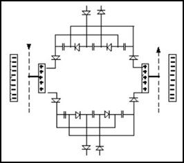 could not reduce the function generator signal.
There seems to be no way around the original circuit. To reconstruct this, however, it is necessary to remanufacture the type 70-L-7 electron tube and to manufacture the field-electric diode. In addition, a signal generator that produces a soliton wave would be required. The efficiency of the quarter sine wave used by Tesla should also be tested, which can be easily produced with the Arbitrary program. Last but not least, money and donations would also be needed, because these two developments run in parallel cost a lot. Professional cooperation would be necessary. The collaboration of specialists with decades of experience could significantly speed up this process and bring the successful reconstruction and re-production of the Tesla coil and the Tesla converter closer.
By using the Tesla converter, we can become independent from the power. The state and multinational companies cannot settle on us, they cannot raise energy prices without restraint. We cannot be blackmailed by oil and gas producing states. We do not become victims of stock market speculators. The electricity we produce is the cleanest green energy because it does not come from power plants. Its worldwide use also cleans the air, and global warming can be stopped. In the event of extreme weather, tens of thousands will not be left without power due to fallen trees falling on power lines. The landscape and the environment are no longer disfigured by the high-voltage wires and steel poles criss-crossing the Earth's surface. Free energy also eliminates inflation, since the purchase price of energy accounts for most of the production costs in agriculture. And in the event of a possible world war, we will not sink back into the Middle Ages. Home-produced free energy enables the continued operation of our civilizational achievements. We are not cut off from the outside world.
Budapest, 10 May 2024
![]()
They also reject applications for perpetual motion machines out of hand. They justify their decision by saying that, according to the current scientific position, free energy does not exist. So these structures cannot work by themselves. A mechanical structure only comes into operation if energy is fed into it. However, the energy source can be of various kinds. There is also energy locked in matter. One such source is radioactivity. The half-life of the isotope thorium 232, for example, is 1.405•1010 years, which is well beyond the age of the universe. Since it has existed, it has been continuously radiating energy from itself. And it will continue to do so for a long time.
Inventors use a more harmless energy source. This is mostly magnetism. The simplest means of its manifestation is the electromagnet. However, there is also a form of magnetism locked in matter. This is the permanent magnet. With electromagnetic excitation, the domains in magnetically conductive materials, such as soft iron, turn in one direction, and remain that way after the excitation is stopped. After that, they radiate magnetic energy for decades without their strength decreasing significantly. The creators of perpetual motion machines take advantage of this. Their structure is started by hand, and further movement is provided by the attractive and repulsive forces of the built-in permanent magnets. Strong magnets also swing it through the dead center. This is helped by the ether, which swings the magnets forward due to the force of inertia. (When the bus brakes, we lean forward. It does this with other materials as well. When the permanent magnet slows down due to gravity, the ether pushes it forward. Then it enters the force field of the next magnet, which swings it further.) Father Peregrinus built such a structure as early as 1269.
Why make a big deal out of this? Why should the energy locked in matter be declared a quackery and fought against with fire and iron? Free energy generating devices containing moving parts (mostly electrical machines) also use this energy. They generate electricity from it. Árpád Bóday and his son also used this physical phenomenon for their invention. In order for an electric motor to rotate, two electromagnets are needed, which repel each other at the appropriate rate. The same is true of the current-generating dynamo. If one of the electromagnets in the dynamo is replaced by a permanent magnet, the energy required to move it is reduced by half in most cases. The difference is declared free energy and the device is tried to be patented. Why did they have to be cursed for this? Why should inventors who produce excess energy be banished to the margins of science? (Today, the wound rotor of the alternating current motors that drive electric cars is also replaced with permanent magnets. This eliminates the need to excite the rotor, which reduces the load on the battery. This in turn increases the distance that can be covered with a charged battery. Tesla cars also have such an engine. When Elon Musk decided to choose this solution, did scientists also call him a quack?) [57]
There is not a single scientist who would think about the operating mechanism of these devices with a clear head. If they did, they would quickly realize that this is not about free energy. Energy really cannot be created from nothing. For this, inventors either use hidden energy or call on the ether to help. Tesla, for example, used resonance to produce free energy. This is also a physical phenomenon that exists. Why curse anyone who uses it? The negative internal resistance of some diodes and electron tubes also produces excess current. Is this also a magic trick? According to narrow-minded scientists, yes. Because their idol, Einstein, concluded in a botched experiment that there is no ether. They still cling to this statement made at the beginning of the last century, which set back the development of science by 100 years. We have been struggling in this pit for a century and are unable to get out of it.
Incidentally, there is a much more intense form of energy locked in matter. This crystal, called oreikhalkos (flint), had such a strong magnetic radiation that in previous civilizations the gods used it as a ray weapon in their wars against each other. The method for this can be found in mythology. The Greek gods called this metal-like crystal adamos (uncontrollable) and made magical weapons from it. All we know about this is that it was light as a feather and its power was unimaginable. There was no material in the world that the adams couldn't cut in an instant. Despite its light weight, it was so hard that it couldn't even be scratched.
The shamir used by the ancient Jews was probably made of this crystal. It emitted such a strong magnetic ray that it cut through diamonds like a knife through butter. Unfortunately, this crystal is not available in our world because it is only found in the mountains of Atlantis, and this continent sank along with its mountains. They also built this crystal into the top of their pyramid, whose magnetic radiation was so strong that it broke through to the surface from a depth of several kilometers. This is what causes the Bermuda Triangle phenomenon. According to the American prophet Cayce, Atlantis will rise to the surface in a few decades. We will see if the previous civilization will be willing to help us solve our energy problems.
We may not have to wait that long. Edgar Cayce also predicted that we would find the Hall of Records in Egypt, where the knowledge of Atlantis is stored. In this, a huge amount of books and parchment scrolls transmit to us the entire knowledge of the Atlantean civilization. Western scientists have been exploring the Great Pyramid for years with ground scanners. They were looking for hidden chambers. Instead, they found only narrow shafts, which contained nothing. (One was a ventilation opening, the other was an astronomical observation shaft.)
However, behind the Queen's Hall, they found a previously unknown chamber, in the heart of the pyramid. French, Japanese and American scientists have also probed the area around the pyramid using the electromagnetic scanning method. They have already found several cavities here, which were filled with sand. We do not yet know what was hidden in the sand used as a preservative. They also found the Hall of Records, which is not located in the pyramid, but under the Sphinx. This is an 8.8×5.5 meter room, which is also filled with sand. Even in the Sphinx there are three smaller cavities, in which the ground scanner detected objects harder than sand.
Seeing all this, Egyptologists were overcome with bewilderment and bewildered shock. Some of them are vehemently opposed to opening the hidden chambers. Technical difficulties also hinder this operation. It would be possible to penetrate these cavities by forcibly breaking down the walls, but there is a fear that the stones falling from the vault due to the collapse of the static balance would bury the researchers under themselves. Certain signs indicate that there is a much simpler and safer way to enter the chambers. However, the location of the secret doors created by the builders and the method of operation are unknown. According to ancient writings, the place of the end of the hall under the Sphinx, which hides the Atlantean documents, is marked by the coincidence of the top of the pyramid and the shadow of the Sphinx on an October day. Then the door will open by itself. We will find out the exact date later, when we are mature enough to receive these knowns.
In the meantime, it is worth studying the supermagnet received from the Jarga (Iarga) civilization. Our cosmic neighbors gave it to the Dutchman Stefan Denaerde as a gift to help us with our technical development. This material is eerily similar to adamantium. It is much harder than diamond, but lighter, a layered superconducting metal that can be made supermagnetic. They did not reveal what it is good for, but a light, hard supermagnet can be made into many things. An antigravity drive or a generator that produces free energy. (Electricity can also be easily extracted from the Hamel drive. All you have to do is turn the magnetic disks in it and place a soliton around or under it.)
It would be advisable to subject the gift from the Jarga civilization to scientific examination. It would be necessary to determine whether this is a natural crystal or artificially produced. If it is artificial, its composition can be determined by scintillation analysis. If it is a combination of elements found on Earth, then we could also produce it, which would mean a huge step forward in both space exploration and in reforming our energy supply. Let's not count on our scientists to help us with this, because they already get a brain hemorrhage from the free energy produced by permanent magnets. And they don't even know about oreichalkos.
Instead, they want to solve the energy problems of our civilization with a fusion nuclear power plant. The essence of releasing energy through fusion is to stop the rotation of the atomic nuclei that are to be combined around their axes and press them together. As a result of the fusion of the atomic nuclei, a huge amount of energy is radiated. This physical phenomenon takes place during the use of the hydrogen bomb. (In conventional nuclear power plants, two smaller atomic nuclei are made from a larger atomic nucleus, and in a fusion power plant, two smaller atomic nuclei are made from a larger one, by combining. This process also takes place in the Sun, under natural conditions.) They are trying to tame this phenomenon, to reduce it to a small amount, so that only enough energy is generated, which is necessary to operate the thermal power plant connected to it. However, this is not possible. In order to start the nuclear fusion, a temperature of 100 million °C and a pressure of 100 thousand atmospheres are required. At this temperature, the electrons of the gas atoms are torn off from the atomic nucleus, and the gas turns into a mixture of electrically charged atomic nuclei and electrons, plasma. Since there is no container that can withstand these extreme conditions, and the heat removal would also be very large, the plasma particles to be combined are suspended in a magnetic field. However, an extremely complicated and expensive structure is required to magnetize and rotate the gas atoms.
The reaction has not yet been maintained for more than a few
hundredths of a second, and this result has only been achieved in small power
plants of a few kilowatts. The Russian-made Tokamak device was first used for
the experiment. However, its power is low. Therefore, a 500 MW version was
planned. ITER is being built in France. The total cost of the investment
reaches 12 billion euros. 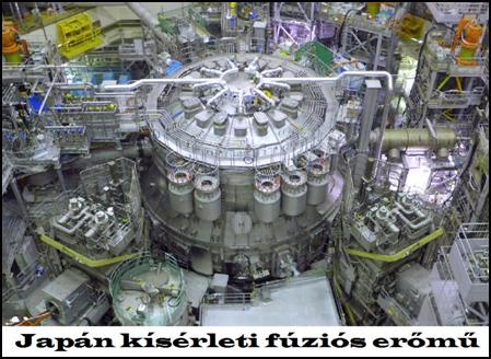 The Tesla
converter could be reconstructed for one
millionth of this amount. However,
neither politicians nor scientists are
willing to acknowledge this. Most of them are not even willing to read
the proposal. As soon as they find out that it is about energy production based
on esoteric principles, they will dismiss it
with a wave of their hand. Those who are engaged in the extraction of
free energy are considered occultists and do not want to hear about them. They
do not want to be suspected of witchcraft, to become ridiculous due to a
possible scandal. They are afraid of their careers, they are afraid of being
held accountable for wasted money.
The Tesla
converter could be reconstructed for one
millionth of this amount. However,
neither politicians nor scientists are
willing to acknowledge this. Most of them are not even willing to read
the proposal. As soon as they find out that it is about energy production based
on esoteric principles, they will dismiss it
with a wave of their hand. Those who are engaged in the extraction of
free energy are considered occultists and do not want to hear about them. They
do not want to be suspected of witchcraft, to become ridiculous due to a
possible scandal. They are afraid of their careers, they are afraid of being
held accountable for wasted money.
The fusion power plant is safer than traditional nuclear power plants, and its operation is also much cheaper. There is no air pollution. During its operation, only helium and oxygen are produced. The raw material deuterium can also be produced in unlimited quantities. (It is extracted from seawater.) However, the other disadvantages of power plant electricity supply would still exist. The power transmission system, the electricity distribution system, would remain, which means that we would still have to pay for electricity. We would still be at the mercy of stock market speculators who are driving energy prices sky high. Power outages resulting from damage to the power line would also cause a lot of annoyance. The fusion nuclear power plant is therefore nothing more than an expensive game for scientists.
It is like CERN in Switzerland. The institution, built by the European Research Organization at a cost of more than 10 billion euros and maintained at a cost of more than 1 billion euros per year, employs geniuses from 50 universities in 80 nations. The more than 14,000 scientists are busy researching the chaotic world of atomic particles. All of Europe's development resources were poured into the CERN particle accelerator for ten years, but they still failed to find the "divine" particle by colliding protons. After a failed proof, Einstein declared that there is no ether. This statement became an axiom in physics and hindered the development of science for a hundred years. However, it shouldn't have been, because Einstein wasn't sure about this statement either. Later, he stated that the ether should be smuggled back into physics one day.
There have been several attempts to do this recently. The most intense search for the "god particle" is in the CERN particle accelerator in Geneva. They gave the ether particle this name because they don't dare to admit their true colors. If they called it the etheron, they would be admitting that they had made a huge blunder by denying the existence of the ether. However, they have not found the god particle. The reason for this is that scientists of our time are making the same mistake that their predecessors, whom they revered as idols, believed that the etheron is an extremely small subatomic particle. However, ether is not matter, but energy, and therefore its existence cannot be demonstrated by material means.
Its presence in our world should be proven in other ways. CERN researchers have recently called the divine particle that fills the universe the Higgs field. Other scientists call this medium the Dirac sea. However, the English physicist Paul Dirac did not deal with subatomic energy particles, because the quantum physics he developed was stuck at the smallest particles of matter, which are also called “subatomic”, but not energy particles, but material particles. Quantum physics researchers would also do better to switch to researching the ether, taking the advice of aliens from the planet Ummo. According to the Ummites: “The search for more and more subatomic particles is a pure illusion. These particles are different manifestations of a single fundamental particle (the ether). These manifestations depend only on the conditions of the investigation and the energy vector used.”
Unfortunately, in recent decades, Satanic-inspired counter-revelators have managed to discredit the insights of esotericism to such an extent that any such proposal is a “red flag” in the eyes of the authorities. Even extraterrestrial civilizations have been urging us for decades to find the common source of all energy, but we have not heeded their advice. Although they manually created the world and have been helping us develop for thousands of years, they officially deny even their existence. That is why we cannot get out of our current troubles, and that is why we stagnate in one place from generation to generation. The evil forces seeking to destroy our civilization have managed to completely block the only possible way out for us.
Budapest, 23 October 2024
![]()
In July 2025, I was forced to stop developing the Tesla generator. I uploaded the results I had achieved so far to the Internet and told my readers that due to the lack of money and support, I was suspending this development as well. So what should I do now? How to continue? I didn’t have to think about it for long. The next day, a letter arrived. A retired reader of mine wrote that he had accidentally come across my article about the Tesla converter and found it so interesting that he couldn’t stop reading it. He was very sorry that I had to suspend this development as well, because no one was willing to manufacture the two missing parts. György Halász offered me a way out of this situation. He suggested that I try to reconstruct the Egyptian Djed pillar.
After reading the literature daily for more than 30 years, I knew about the existence of the Djed pillar, but I didn’t know what it was for. I looked it up on the Internet. It turned out that this was an ancient power source. Thousands of years ago, there was no mains electricity, and they didn't even know about the existence of electricity. Nevertheless, electricity was used in ancient times, mostly for lighting. One way of doing this was by using galvanic cells in clay jars, to which large fog lamps were connected. This was used to illuminate the walls of the pyramids, on which intricate figures were painted.
The other way was to use the Djed Pillar. For a long time, we only knew that it had to do with electricity. Later, we found out that it could have been an eternally burning light-emitting device. It did not discharge after a while, like the galvanic cell. It obtained the energy needed for lighting from space. The energy that fills the universe was not yet called ether, but this energy has existed since the Big Bang and is inexhaustible. It fills the entire universe, and everything comes from it. Even matter. In its elemental state, however, it is energy, which was tapped in ancient times with the Djed Pillar.
The Djed Pillar works very similarly to the Tesla Coil. The difference is that the Tesla Coil is a high-voltage transformer, where a primary coil with one or two turns excites a secondary coil with many turns. When tuned to resonance, several thousand volts are generated in it, which is radiated in the form of a corona discharge at the end of the coil. The Djed Pillar is a series LC resonant circuit, the coil of which also radiates energy. In the Tesla converter, a very large amount of energy is also generated in the secondary coil. However, this amount of energy is not generated when a coil and a capacitor are connected in series or parallel. This energy occurs in the case of resonance. (Resonance is caused by etheric particles as described in the study Resonance Frequency Excitation.) The Tesla Coil probably radiates electromagnetic energy. But what is it that radiates from the Djed pillar?
If it is electromagnetic, it is dangerous. Electromagnetic waves cause blood cancer (leukemia) in the body. It has been proven that more people die of cancer within 100 meters of high-voltage power lines than those living further away. Even more dangerous is microwave radiation, which is also carcinogenic. When it emits electrical waves, it upsets the energy balance of our meridian system, which causes various diseases. What is worse is that the magnetic waves penetrate walls and furniture, and the gravitational radiation heats the environment. After a while, its concentration becomes so high that it causes spontaneous combustion. Then the entire building burns down. This “dragon fire” is so intense that even concrete and metals burn to dust. It cannot be extinguished because water conducts electricity, so sprinkling it has the same effect as trying to put out a regular fire with gasoline. That is why the laboratory of Tesla and Raymond Rife's colleagues burned down.
The longitudinal wave is even more dangerous because it threatens our lives. It overcharges or discharges our meridians, which causes rapid illnesses that end in death. First it causes nausea, blurred vision, and then it puts us in bed. Doctors cannot help us because they cannot determine the cause of the illness with the diagnostic methods they use. The only way to protect yourself is to install it away from your home in a concrete pit that does not contain iron rods, and to insulate it airtight, and to bring the generated electricity into your home with an underground cable hídden in a PVC pipe. You can protect yourself against concentrated etheric radiation with sheepskin, because the wool deflects and scatters the magnetic waves, but you can't make your family members hide in a suba day and night with a wool cap on their heads and put leather gloves on their hands with the fur facing outwards. The most fortunate case is if the Djed column emits electromagnetic radiation. This can easily be protected against with a Faraday cage.
To determine the nature of the danger, instrumental measurements would be needed, but for this, the Tesla converter or the Moray converter would first have to be reconstructed. This is not impossible, because many people are dealing with this topic recently. In a blog post on free energy, one of the commenters boasted that he had managed to reconstruct the Moray converter. He said no more than that. He did not leave an email address or phone number, so it is impossible to contact him. Fortunately, there are more talkative developers. The Internet is full of free energy production videos. Most of them are scams. However, there are also remarkable and even astonishing developments. One of these is the invention of a retired engineering teacher, János Veres, who reconstructed the Egyptian Djed pillar. He demonstrated the operation of the prototype made from modern components in a video. Web: https://fuzeshirek.hu/valoban-letezik-a-terenergia/ (If it doesn't open when you click on it, copy and paste it into your browser's Address bar. The film starts at 18 minutes.) However, he did not reveal anything about the essence of the invention, the "special semiconductor".
The reason for this is that, like many inventors, he wants to get rich from his invention. However, it would be good to stop this secrecy and join forces with others to find a way out, because a great danger is lurking for our civilization. Due to global warming, the air temperature is rising year by year. In Pakistan, this year, +50 °C was already measured, which is impossible to endure permanently. In 2025, 75 thousand people lost their lives in Europe due to the scorching heat. This loss will rise sharply every year. As a result of the drought caused by the lack of precipitation, forests burned in a larger area than ever before. (In Southern Europe, the United States, Canada, and Asia.) This situation will intensify, and we will all be like Hollywood stars. In the luxury district of Hollywood, more than 10 thousand luxurious villas were razed to the ground due to the devastating fire in Los Angeles County. In addition to Bel-Air, Beverly Hills, Calabasas, Hollywood Hills and Malibu, Palisades was also reduced to ashes. Expensive furnishings were burned, and luxury cars in the garage.
Celebrities who flaunted their wealth had to leave their ostentatious homes so quickly that they often could not take their money, jewelry, or even their documents with them. (This is also the case in forest fires. The residents of villas built in the lap of nature refuse to leave their castle-like buildings with amazing views. They trust that the firefighters will put out the fire in time and that it will not reach their homes. When they see that the flames have almost surrounded them, they leave everything behind and flee in panic.)
Global warming could be prevented by reducing the carbon dioxide content of the atmosphere, but this will not work. Neither the Kyoto Protocol nor the Paris Agreement has been complied with. Air purification is also greatly hindered by poverty. In our country, it is impossible to walk through the villages in winter, because one would suffocate in the smoke. People living in extreme poverty heat their homes with PET bottles, used car tires, and discarded shoes. In order to eliminate this situation, a generator that produces free electricity would be essential. If the pursuit of profit does not allow this, according to extraterrestrial civilizations, we will burn alive along with our money.
 The Djed
column looks like it contains 4 capacitor plates and a coil with a few turns
underneath. The special semiconductor device is also hidden here. It is inside
the column. We know nothing about it, because the priests did not even think
that there could be anything inside. Therefore, they did not break any Djed column to see what was inside. The Djed column did
not need a lamp. The 4 capacitor plates placed one under the other
created such a field strength that it lit up by itself. Its strong magnetic
radiation ionized the air, and the plasma
shell thus formed lit up. (The attached picture shows the Djed column
placed near the pharaoh.) It even had a switch. It was a two-pronged metal
fork. If the priests touched this long-handled fork called Was to the upper
capacitor plate, the excitation stopped. As can be seen in the attached steps,
this fork stopped the excitation by sticking the two-pronged end of the fork into the ground and grounding the
capacitor plates with the other pointed end. When it touched the coil, the
excitation started again, but this may have
been done with the Ankh cross[58] shown in the picture.
The Djed
column looks like it contains 4 capacitor plates and a coil with a few turns
underneath. The special semiconductor device is also hidden here. It is inside
the column. We know nothing about it, because the priests did not even think
that there could be anything inside. Therefore, they did not break any Djed column to see what was inside. The Djed column did
not need a lamp. The 4 capacitor plates placed one under the other
created such a field strength that it lit up by itself. Its strong magnetic
radiation ionized the air, and the plasma
shell thus formed lit up. (The attached picture shows the Djed column
placed near the pharaoh.) It even had a switch. It was a two-pronged metal
fork. If the priests touched this long-handled fork called Was to the upper
capacitor plate, the excitation stopped. As can be seen in the attached steps,
this fork stopped the excitation by sticking the two-pronged end of the fork into the ground and grounding the
capacitor plates with the other pointed end. When it touched the coil, the
excitation started again, but this may have
been done with the Ankh cross[58] shown in the picture.
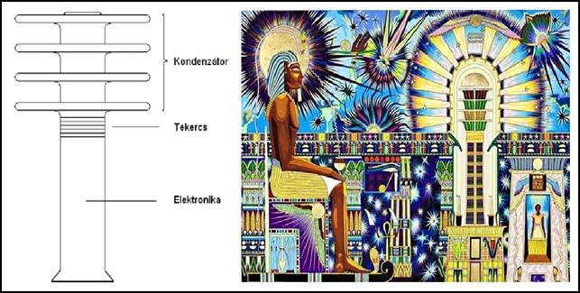 After
the flood, the extraterrestrials who recreated our civilization and the peoples
of Atlantis who migrated to the Middle East and Egypt provided us with several
types of ever-burning lamps. The most intense light among them was provided by
the Djed Pillar. (While in China the Yellow Emperor helped them, in Egypt
Osiris and his wife Isis helped them. Their power was ended by their brother
Seth, who joined the service of Satan, by killing them.)
After
the flood, the extraterrestrials who recreated our civilization and the peoples
of Atlantis who migrated to the Middle East and Egypt provided us with several
types of ever-burning lamps. The most intense light among them was provided by
the Djed Pillar. (While in China the Yellow Emperor helped them, in Egypt
Osiris and his wife Isis helped them. Their power was ended by their brother
Seth, who joined the service of Satan, by killing them.)
However, we do not need a lamp that burns forever, but free electricity. This is also easy to produce. Moray solved this by placing another solenoid next to the coil of the series LC resonant circuit. In this case, the energy emitted by the coil was not converted into light, but induced an electric current in the solenoid. By connecting the solenoids in cascade (in series), Moray was able to extract more kW from his generator. This solution is proven by the contemporary photograph that can be seen in a yellowed newspaper. It consisted of only a few capacitors and an air-core coil. Its production cost would not exceed $ 50 even today. Since it contains no moving parts, its lifespan is almost infinite. If a solenoid is not overloaded, it will work for decades. If the capacitors do not dry out, they will also remain functional for decades. Film capacitors enclosed in a plastic case are not threatened by this danger.
 The
advantage of using air-core coils is that their production cost is an order of
magnitude lower than the iron-core (transformer) solution of the Tesla
converter. However, their efficiency is lower. Moray made two types of devices.
With one, he produced free energy (free current). His generator provided 3.5
kW, which provided the power needs of a household at the time. His other device
was a longitudinal receiver, which worked as described above, and used the
ether sea that permeates the universe everywhere as a carrier wave. It was possible
to listen to distant conversations with it, without
a microphone. The soul of both devices was the “special semiconductor”, the
nature of which Moray also kept secret.
The
advantage of using air-core coils is that their production cost is an order of
magnitude lower than the iron-core (transformer) solution of the Tesla
converter. However, their efficiency is lower. Moray made two types of devices.
With one, he produced free energy (free current). His generator provided 3.5
kW, which provided the power needs of a household at the time. His other device
was a longitudinal receiver, which worked as described above, and used the
ether sea that permeates the universe everywhere as a carrier wave. It was possible
to listen to distant conversations with it, without
a microphone. The soul of both devices was the “special semiconductor”, the
nature of which Moray also kept secret.
However, he told how he developed it. The soul of this component was a special stone. This stone was transported on a railway carriage and he took a handful of it because of its interesting color. As it turned out later, this stone was a germanium crystal. The application of this semiconductor material is confirmed by the fact that, unlike silicon diodes, germanium can operate at very high frequencies and has half the opening voltage. Moray recognized the semiconducting properties of germanium and made a valve from it, which made it possible to develop an energy generator. Fortunately, this secret did not remain a mystery forever. Today, it has been reconstructed. Several inventors use it, but we know nothing about its nature, because everyone keeps its production method secret. However, with some trial and error, you can find out what kind of diode should be used for this purpose. This small “black box” is probably a low opening voltage diode or transistor (germanium, gallium arsenide).
An even greater mystery is the way the two converters work. After careful study, it turned out that the Moray converter and the Tesla converter work essentially the same way. The Moray converter is built from series LC resonant circuits, while the Tesla converter is built from parallel LC resonant circuits. The main difference is that the Moray converter uses air-core coils, while the Tesla converter uses iron-core coils. The biggest surprise is that energy is extracted from the ether in the same way as the Djed column. This requires resonance. However, energy multiplication does not occur in the usual way. In the electromagnetic circuits we use, the series and parallel resonant circuits tuned to resonance increase the energy fed into them by a maximum of three times. Here, however, a single stage generates several thousand volts. This astonishing phenomenon is caused by the fact that the series and parallel LC resonant circuits are not used in the usual way, but as cumulators. The diode placed between the capacitor and the coil continuously charges the coil with energy. The reverse flow of current, i.e. the formation of the usual resonance, is prevented by the reverse voltage of the diode.
He called this operation Tesla valving. He noted in his
diary that the LC elements should not be allowed to resonate with each other.
Nevertheless, this resonant circuit must also be tuned. Just like conventional
series and parallel resonant circuits. The construction of the Tesla converter
was made difficult by the fact that the primary and secondary coils of the
transformers had to have exactly the same mass to the gram. The wire thickness
and number of turns could be varied, but their mass could not. Tuning a
parallel LC resonant circuit to resonance is also more difficult. This is why
no 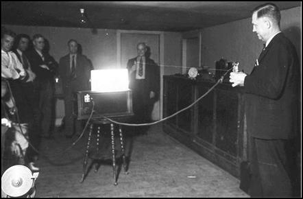 one has yet been able to
reconstruct the Tesla converter.
one has yet been able to
reconstruct the Tesla converter.
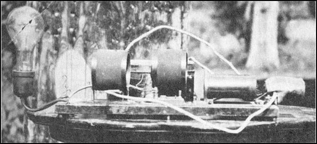 Unfortunately, neither the Tesla converter nor the Moray converter and Moray transmitter manufacturing method have survived. Both
inventors took their secrets to the grave.
Tesla did give them to a manufacturer, but they went bankrupt and no
one else needed them. Moray never got
there. He tried to patent his invention, but
the US Patent Office refused. They said it was too futuristic. Like Tesla, Moray also gave several public demonstrations of the operation of his
devices. This aroused the interest of the entire scientific world. Physicists
also attended these demonstrations, and when they looked inside the device and
saw nothing but a few coils and capacitors, they thought it was a hoax. Moray
even published a circuit diagram of his generator. This did not convince them
either.
Unfortunately, neither the Tesla converter nor the Moray converter and Moray transmitter manufacturing method have survived. Both
inventors took their secrets to the grave.
Tesla did give them to a manufacturer, but they went bankrupt and no
one else needed them. Moray never got
there. He tried to patent his invention, but
the US Patent Office refused. They said it was too futuristic. Like Tesla, Moray also gave several public demonstrations of the operation of his
devices. This aroused the interest of the entire scientific world. Physicists
also attended these demonstrations, and when they looked inside the device and
saw nothing but a few coils and capacitors, they thought it was a hoax. Moray
even published a circuit diagram of his generator. This did not convince them
either.
Moray even allowed the scientists who attended the demonstrations to take his device apart and study its components in detail. This only increased their disbelief. They searched in vain, but they could not find the source of the energy. They did not deny the operation of Moray's device. After conducting all the existing tests on it, they were forced to admit that it worked. This angered them greatly. Two scientists from Columbia University stated: "We wish him to destroy his damned device so that he would not have the opportunity to experiment further." In the end, due to disbelief, envy and professional jealousy, Moray was unable to sell or put his devices into production. After his death, interest in his invention intensified, but it was too late. A delegation even arrived from Japan to obtain the method of production from his widow. The widow got tired of the constant harassment and threw all the copies and documentation of the invention into a nearby river.
Later, these inventions were forgotten. Scientists of our time also deny the existence of these converters. They say that the reports about the Tesla converter and the Moray converter are just legends. They are not interested in the fact that photographs were taken of the demonstrations in the 1930s, and that hundreds of newspaper articles both in America and abroad reported on the existence of these devices. Moray wrote several books on the use of space energy. One of them was published under the title “Energy Sea Around the Earth”. Its Hungarian translation can be found on this website: https://joubert.hu/attachments/article/53/moray%20knyve%204.%20kiads.pdf
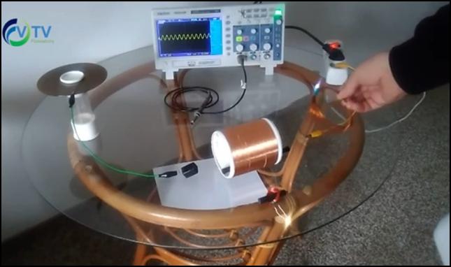 After the somewhat lengthy introduction, let's
move on to reconstructing the two converters. Let's start with the
easier-to-implement Moray converter. After watching the report with János Veres,
we don't have to fear failure. He has already done the hard part of the work.
He reconstructed the Djed column with modern components, which creates the
theoretical basis of the Moray converter. The single-stage resonant circuit he
invented provides 10 W of energy from nothing, which is a huge achievement. We
only need to multiply this energy. If the additional stages operate with
similar efficiency, we will soon reach 5 KW, which already satisfies the needs
of modern households.
After the somewhat lengthy introduction, let's
move on to reconstructing the two converters. Let's start with the
easier-to-implement Moray converter. After watching the report with János Veres,
we don't have to fear failure. He has already done the hard part of the work.
He reconstructed the Djed column with modern components, which creates the
theoretical basis of the Moray converter. The single-stage resonant circuit he
invented provides 10 W of energy from nothing, which is a huge achievement. We
only need to multiply this energy. If the additional stages operate with
similar efficiency, we will soon reach 5 KW, which already satisfies the needs
of modern households.
But first, we need to find a diode that can effectively perform the function of the valve. From my childhood DIY, experimenting with detector radios, I had a lot of germanium diodes and transistors left over. I took them out and tried them out one by one. But first, I had to make the antenna and the capacitor plate. I didn't have much choice. All I found was a 2 mm thick aluminum plate among my scraps. I cut out a 24 cm diameter circular plate from it with a jigsaw. Like Mr. Veres, I didn't cut a hole in the middle because I don't think the Djed column was made by drawing circular metal plates onto a porcelain or ceramic column. They formed flat bowls. They placed the metal disc on top of this, and then placed the next bowl on top. Finally, the whole thing was covered with porcelain. (In the blog posts, someone claimed that the ribbing seen on these bowls is winding, and the resonance of the two coils produces the free energy. However, this is not the case. These notches are ribs that strengthen the side walls of the bowls.)
If I manage to reconstruct the Moray generator, I will also try the annular plate. I would be surprised if it had a larger capacity than the disk-shaped one. I have not heard of a perforated capacitor yet. Well, let's see what the circular plate antenna can do. It is smaller than the approximately 30 cm diameter shown on the Djed column, but it will be good for testing. I placed the aluminum disc on the mouth of a 0.5 liter mason jar. I connected the oscilloscope's test cable and clipped its ground wire to the protective ground of the connector. I was in for a big surprise. I wondered why Mr. Veres' oscilloscope showed a sine wave with a plus and minus half-period. I also had the same thing. This is probably due to the 50 Hz mains current leaking into the environment. I pressed the Measure button on the oscilloscope. Everything showed, except for 50 Hz. The frequency display jumped between 120 Hz and 62 kHz. The only way I could determine the frequency of the sine wave was to measure the duration of a period on the time axis. It was 20 ms. From this, it is easy to calculate that it is indeed 50 Hz. Broad-frequency ether noise is superimposed on this, which makes the sine wave noisy. That is why the oscilloscope cannot measure a stable frequency.
This situation immediately raises several problems. Mr. Veres' invention is actually a high-power noise generator. It makes free energy from the electrosmog that surrounds us everywhere. This is not a big problem, because it only uses this signal for excitation. The amplitude of the voltage detected by the oscilloscope is 120 mV, and its current does not even reach 1 mA. This does not mean electricity theft, because this small energy consumption does not burden the mains electricity. This consumption is so small that it doesn't even start the electricity meter. When I touched the capacitor plate, the amplitude jumped to 2 V. However, its current remained very small. However, it can have a harmful effect on health. The ubiquitous electrosmog disrupts the microampere communication between our cells. It is no coincidence that in our modern age so many people get sick and die from cancer. In ancient times, cancer was a rarity.
The 50 Hz excitation causes additional problems. This generator cannot be used in places where there is no mains electricity, where there are no high-voltage power lines. And the natives of the primeval forests would also need a wireless power generator. They also want to listen to the radio, watch TV, and use the Internet. But not only them. Even those where there is no wired electricity supply. For example, in Inner Mongolia, in the Sahara, but also in civilized countries, there are areas that are not provided with wired electricity (e.g. the farm world). This area will become larger and larger, because if local electricity generation becomes widespread, the transmission lines will be dismantled and the wiring of buildings will cease. Every device will power itself, with a factory-installed small Moray or Tesla converter. Then this generator will have to be redesigned. It will continue to work, because the Djed column also worked in ancient times, only the excitation current will be smaller. The ether is not able to provide a signal as large as the leaking mains current.
Before we move on to the valve of the signal provided by the capacitor plate, let's see what it is advisable to make this type of antenna from. Copper, aluminum, corrosion-resistant steel or tin (galvanized or phosphated iron sheet). Since I don't have plates made of such material, I went out to the kitchen, where I found pot lids made of different materials. It turned out that the material of the plate is irrelevant. They all produce the same amplitude. So let's stick with aluminum, because it's the cheapest. The thickness doesn't affect the signal amplitude either. However, it's not advisable to go below 2 mm, because the thin antenna is vulnerable and can deform.
However, the surface area of the circular antenna greatly affects the capacitance. The larger its diameter, the greater the signal it provides. However, it's not advisable to increase its size to infinity. Nobody wants to put a table-sized generator next to their heat radiator. The big question is whether multiple capacitor plates stacked one on top of the other are necessary. According to superficial measurements, this doesn't affect the signal amplitude either. The Djed column probably used multiple plates to increase the intensity of spark formation. For clarification, this measurement should be performed again on the finished generator.
However, in order to protect our health, an important measurement should not be postponed. This device will probably emit electromagnetic waves into its environment. At high intensity. This attacks the internal organs and can cause cancer. However, it is easy to protect against electromagnetic waves. It must be shielded, enclosed in an iron cage, and grounded. The question is what the antenna has to do with this. I brought the tin pot (washing pot) used for steaming from the chamber and placed it on the antenna. The signal amplitude jumped from 120 mV to 200 mV. I grounded the pot. It then decreased to 40 mV. So the antenna cannot be shielded, but it does not need to be, because it does not emit waves of significant strength. Unfortunately, it cannot be mounted on top of the device either. The metal housing that shields electromagnetic radiation increases the amplitude of the signal, but if the metal housing is grounded, it drops to 30 mV. Therefore, the antenna made of a circular plate must be placed further away from the device. To avoid dust, it can be covered with a densely woven textile. This design allows the generator to be turned off quickly. To do this, you just need to touch the antenna.
This excitation method requires grounding. Without it, the generator will not work. Electrons only start when there is a voltage difference. Lightning also needs the Earth to discharge the charge accumulated in the clouds. Tapping the ether also requires the opposite pole to create the voltage difference. This is the Earth. In countries where there is no protective grounding, a larger copper plate must be dug up or a copper rod must be beaten off and the generator's ground point soldered to it. (Screwed connections are not recommended because they can cause corrosion and contact defects due to oxidation and moisture.)
Well, then let's try to solve the most difficult task, valving. Tesla used a cold cathode electron tube for this purpose. Its opening voltage is low and its closing voltage is high. In other words, it is particularly suitable for valving, that is, for continuously charging energy. Moray used a germanium crystal, which he somehow made suitable for valving. The opening voltage of the germanium semiconductor is 0.3-04 V, or 300-400 mV, and the circular plate antenna does not provide that much. Therefore, the germanium diode will not open. Let's see what the situation is. I will take out a dozen different types of germanium diodes and try them one by one.
For the test, I wound a solenoid from a Ø 0.45 mm thick copper wire. Mr. Veres used thinner wire, but that's all I had left from previous experiments. So I wound the thicker wire onto a longer coil body. To wind solenoids, use PVC pipes of different diameters, which are used by plumbers. These are easily available at hardware stores. The solenoid will probably heat up at the end of the stages. For this reason, we will have to order a textile bakelite coil body there, which will not be cheap. Since we probably can't wind large solenoids with our transformer winding machine, we will have to make them by hand. In the process, it may slip out of our hands. If it falls to the floor, the whole thing will fall apart. We can start winding from the beginning and get annoyed by the tangled wire. To prevent this, we can tape the already completed coil in sections with insulating tape.
After turning on the three-component series LC resonant circuit, nothing happened. When I measured it with an oscilloscope, the coil shunted the antenna signal. The same thing happened as when reconstructing the Tesla converter. The individual stages loaded each other. The amplitude of the input signal did not increase, but decreased. The reason for this is that the valve did not start. I am in the same place as I was a year ago. I am missing the cold cathode electron tube used by Tesla and the three-layer field-effect diode that I invented. No one is willing to manufacture them, so I cannot manage with the Moray converter either. I tried to find a way out of this predicament. After Mr. Veres managed to create a valve diode, I thought I would try to manufacture the field-effect diode at home.
This diode is actually nothing more than the Esaki diode, supplemented with a high reverse voltage n-layer. I have enough Esaki diodes. Last year I ordered two types. All that was left was to attach an n-type semiconductor layer to the anode of the Esaki diode. Since I can't get it from diodes, I thought about transistors. I tried to do this by burning the emitter-base layer and using the collector layer for this purpose. I selected a few npn silicon transistors, set my power supply to 10 V, and connected them in reverse direction to the base and emitter legs. The base-emitter reverse voltage of transistors is usually 6 V. Despite this, the breakdown did not occur. I raised the voltage to 15 V. This already destroyed the base and emitter layers, but not in the way I wanted. It did not create a short circuit in them, but a break. The two semiconductor layers separated from their terminals.
This would not have been a problem, but with the base leg breaking off, the collector layer could not be used. I repeated this experiment with pnp transistors. The result was the same. Then I tried to short the base and emitter layers in the forward direction. As we know, the opening voltage of silicon diodes is 0.6-07 V, but up to 3 V they only warmed up. The breakdown occurred at 5 V. The result was the same as with the reverse breakdown. It was not a short circuit, but a break. Finally, I tried with germanium transistors. Their base-emitter layer refused to break even at 48 V in the reverse direction. Since I could not regulate this power supply to a higher voltage, I tried the forward breakdown. After I forgot to lower the voltage of the power supply, the consequence was a big bang, and the transistor caught fire in my hand.
So, how do I get an n-type layer? I remembered Schottky diodes. These metal-semiconductor diodes have only one semiconductor layer. It is also n-type. I took out a small version and connected it in series with the Esaki diode. It didn't work either. That damned valve didn't work. The problem was probably caused by the fact that the opening voltage of the Schottky diodes is 0.4 V. But it could also be that the two metal layers interfered with the process. In the meantime, Mr. Halász kept persuading Mr. Veres to reveal the method of producing the field energy diode. He passed on to him the warnings that I had sent him about the harmful effects of irresponsible experimentation. In it, I mentioned that Árpád Bóday Jr. got stomach cancer because of this, which he eventually died of. This didn't impress me either. He wrote back that it was just a scaremongering. Tesla lived to be 83 years old and didn't die of cancer.
I was really annoyed that such a simple, primitive circuit would trip me up. I had to get to the root of the problem. I had to create a series LC resonant circuit. I had to tune it to the resonant frequency with the layer capacitor, and then insert a diode between the two components. Its type doesn't matter, because whether it's operated from 6 V or 12 V, it doesn't matter what its opening voltage is. Since resonant circuits only operate from alternating voltage, I used my signal generator as a power supply. First, I measured the inductance of the coil. In this case, I also set the function generator to a 50 Hz sine wave. This is advantageous because, if the development is successful, the Moray converter can be used directly to power electronic devices. There is no need to connect an inverter afterwards to generate mains current from the energy it supplies.
I set the supply voltage, i.e. the frequency of the resonant circuit, to 6 V, and connected an ammeter in series with it. I calculated the value of the capacitor using the Thomson formula described above. The program assigned a value of 5.6 mF to the 1.8 mH inductance. Something is wrong here. The capacitance of the circular plate antenna measured to ground is 8 pF, not 5600 μF. So there is no question of a series LC resonant circuit here. The optimal efficiency of this resonant circuit can only be set by trial and error. Since the capacitance of the circular plate antenna is given, the diameter, length and diameter of the coil must be increased or decreased. This requires a lot of experimentation.
The situation is therefore getting worse and more incomprehensible. No wonder the physicists who attended the demonstrations got a headache when they studied the circuit diagram of the Moray converter. They were looking for regular resonant circuits, but nothing in this device was regular. They said: “The generator does not comply with the laws of electricity.” It seems that the ether whistles at our laws and works differently. In a completely unusual way, but it works. It does its job for free and well, but getting it to work requires special skills. You can’t learn this in school, because subtronics is not taught anywhere in the world. In a world where the existence of the ether is denied, how can you teach how to deal with it?
I was curious about how the Moray generator would react to the wire antenna. Earlier, to develop the Tesla converter, I had stretched out 25 meters of thick (AWG 12) stranded, tinned, insulated copper cable around my room. (Later, I learned from the literature that solid copper wire is more effective for this purpose. They also used this for detector radios, 4 mm thick.) I connected the end to the oscilloscope. This also provided a 50 Hz, noisy sine signal, like the circular plate antenna. However, the difference was enormous. Instead of the 120 mV signal of the circular plate antenna, the signal of the wire antenna jumped to 2.5 V. At such an amplitude, any semiconductor diode can start the valve. This amplitude far exceeds the 0.6-0.7 V opening voltage of silicon diodes. This means that there is no need for an Esaki diode. However, a wire antenna creates a location constraint. It cannot be used in a car. It also makes the interior of the room look ugly.
Let's see what's the situation with this antenna. I put a germanium diode in place of the Esaki diode. The coil also shunted this antenna. Its voltage of 2.5 V dropped to 0.6 V. This could have started the valve, but it didn't. So let's give it a higher voltage. I turned on the function generator and set it to a 50 Hz sine wave. I set the amplitude to 10 V. Now I inserted a Schottky diode with a higher current into the circuit. Since the resistance of the coil is very low, it shunted the 10 V amplitude to 6 V. This could have made it work, but it didn't. In other words, it worked according to the known laws of electricity.
The diode rectified the sine wave. It became a one-way rectified sine wave, and the coil further shunted its amplitude to 600 mV. When it was converted to a square wave, the self-induction voltage peaks appeared here too, the amplitude of which exceeded the supply voltage. The valve operation did not start either. It seems that this mysterious phenomenon is only willing to manifest itself with the help of the ether. The all-pervading ether somehow causes all the components of the generator to vibrate, and increases the voltage of the components, as well as the current flowing through them. If the excitation is not done by tapping the ether, then no energy multiplication occurs, no free energy is generated. However, the voltage of the antenna performing the tapping is very small. Therefore, for its transmission, a component is needed that opens completely in the opening direction and closes completely in the closing direction. Such a diode can only be produced randomly, through many, many trials.
Morey was the first to succeed. Although he kept the method of producing the detector a secret, he once revealed that he had produced it from a mixture of lead, bismuth, iron sulfate, zinc, molybdenum, germanium and certain impurities. This alloy was able to pass a few mV through it in one direction, while it blocked the current in the opposite direction, preventing the current from flowing back. This alloy is no longer needed today, because gallium arsenide is able to open it by itself at a few mV, although it does not have a significant reverse voltage tolerance. Gallium arsenide practically conducts in both directions. Nevertheless, it is used in many places in electronics, because it has a negative internal resistance. High-frequency generators are made from it. (The Gunn diode, which consists of three n-layers, is also used for this purpose. Despite being called a diode, it cannot be rectified.)
Later expert studies established that the Moray valve was actually a precursor to the transistor. It created a germanium transistor with a low base-emitter opening voltage, in an extremely complicated way. Since the Moray valve was not three-pole, but two-pole, it could easily have been a precursor to the field electric diode I invented. Molybdenum and germanium played the main roles in the production of this diode. Molybdenum disulfide (MoS2) has excellent semiconductor properties. This allowed it to reduce the opening voltage of germanium. After failing to sell it, Moray took his secret to his grave. Today, many have tried to reconstruct the Moray converter, but only a few lucky developers have succeeded. The literature here knows of two people, but both are secretive. Either they want to get rich off it, or they are afraid of the consequences of the widespread use of the device that provides free electricity. It is better not to go into detail about this. So I am in a big dilemma. I don't know what to be more happy about. The failure, or a possible later success.
Returning to the resonance of the ether that permeates all matter, I secretly hoped that if I managed to revive the Tesla converter, I would abandon the first antenna stage and replace it with a cheap Chinese square or sine generator. I feed this with feedback from the output. But it seems that this will not work. Ether cannot be excluded from the excitation by valve. Ether particles still permeate the coil in this case, but only the ether can bring it into resonance. Tapping the ether is only possible with an antenna. Fortunately, an idea borrowed from the Djed column can avoid installing a 20-40 m long antenna. Placing a circular plate with a diameter of 20-30 cm does not cause any problems either in the household or in industry.
Moray transmitter
(Operating description)
Even greater uncertainty surrounds the reconstruction of the Moray transmitter. We know from the press of the time that this was a listening device. It was able to listen to any conversation within 5 kilometers. It was similar to the chronovisor. The development of this device was supported by the Vatican in the early 1970s. The chronovisor was able to transmit not only speech, but also images, although at first only in black and white. However, by the mid-1980s, its color version was also ready. It was presented to the public on October 18, 1986 in Riva del Garda near Lake Garda. It had a great press response. According to the audience, there was no doubt about its authenticity. It was also able to transmit events of the past. Not only was its sound perfect, but also the image display. Those present saw a hologram-like, three-dimensional image on the screen. It is characteristic of the perfection of the ether that it can also transmit the smells prevailing at the location as a carrier wave. However, we do not yet have a sensor to detect this wave and to generate it in the air in front of the screen.
The chronovisor has not been manufactured or widely used. The device began to be used for espionage. It provided information about secret meetings of the great powers. This frightened the Pope so much that he dismantled the device and sent its parts to monasteries in different countries. The operation was carried out with such secrecy that even the guards themselves do not know what they were entrusted with. The chronovisor documentation was placed in a similar way. This danger still exists today. But not only in politics. If it were put into circulation, criminals could keep their potential victims under surveillance in order to pounce on them at the most opportune moment.
Our current level of moral development does not allow its free use either. There are many abnormal, degenerate, primitive people in this world who would use it for voyeurism. Nobody wants their neighbor to watch what they are doing in their toilet or bedroom. However, it could be of great use in law enforcement. With its help, it would be easy to detect the preparations for crimes and the planned actions of terrorists. Therefore, it could only be produced in small series and handed over to the law enforcement agencies and counter-terrorism units of democratic countries.
Moray offered his transmitter for eavesdropping on remote conversations to the United States government, but they did not claim it. (The proposal was made by a representative of the Ministry of War, General Shinkle, who viewed the device and had a long conversation with the inventor.) The Reasons: “The operation of the device is unreasonable from the point of view of the known laws of physics and contradicts the laws of electricity.” According to politicians, it is impossible to obtain energy from an unknown source and in a way that does not comply with the laws of electricity. Remote eavesdropping was also considered impossible. The main problem was the radiant energy often mentioned by Moray. It is still a problem today. Scientists still do not recognize the existence of the ether. The future generation is also being educated to this. They are being instilled with reality. In Tesla’s time, a university laboratory had this slogan on the wall: “All the fundamental laws of physics have already been discovered.”
Patent attorneys also adhere to this. When an invention related to the extraction of free energy comes to them, they immediately reject it. The reason: “The claim is rejected because it will probably result in an inoperable device.” They do not even examine it. They do not even want to see the working device. (Patent offices do not check the functionality of inventions. They do not build them and do not examine them. They check whether the application meets the formal requirements and check its novelty. They are not so interested in functionality that they encourage the inventor to leave out the most important element of the invention from the description and sell it as know-how.) Mr. Veres calls this energy space energy. It does not matter what you call it. The ether is a sea of energy that fills the entire universe. It is available to us in infinite quantities. We just have to use.
With the Moray transmitter, you could also receive radio broadcasts using a rotating capacitor. They sounded crystal clear. Much better than the vacuum tube radios of the time. (By the way, the sound quality of today's transistor and integrated circuit radios does not even reach the quality of the old tube radios. (It is no coincidence that audiophiles buy tube radio tuners and amplifiers, at exorbitant prices.) They lack highs, harmonics, and dynamics.) Therefore, it would be time to switch to the ethereal carrier wave instead of the electromagnetic wave.
Frequency-modulated digital (DAB) radios cannot prevent the deterioration of sound quality either, because they also use electromagnetic waves as a carrier wave. Moreover, frequency-modulated waves cannot be received with ordinary radio, while a program placed on an ether carrier wave can be received by valve control and can be easily amplified and converted into audible sound with the Moray transmitter. However, experts are not interested in this possibility, because they have led scientists to believe that there is no ether. Anyone who claims this is a quack, a charlatan, a fraud. This stupidity not only hinders quality radio and television broadcasting, but also paralyzes space exploration. It does not allow for contact with extraterrestrial civilizations using longitudinal waves. Yet we have known how to do this for 100 years. Tesla's radio worked on this principle. Nobody needed it.
Budapest, October 1, 2025
![]()
POSTSCRIPT
This work can also be viewed in the Hungarian Electronic Library. However, the regularly updated version can only be downloaded from the websites operated by me. The development folder is not available on HEL either. Without the auxiliary files in the compressed folder, the functional description cannot be used perfectly. Path to the attached folder: https://subotronics.com → Subotronics Forum → Subotronics Laboratory → Language: ENGLISH →Paradigm shift. The HTM version can also be found on these websites. However, it only contains the operational description. Also in a hard to read form. Therefore, it is suitable for informational purposes only.
Beginners should also read the study Resonance Frequency Excitation. The experiences described here, as well as instrument and spare parts offers, can be of use to you. This work explores new ways of generating free energy. The work is enormous, so it requires international cooperation. For the cooperation of excellent professionals. That's why I ask that you send me your suggestions so that I can try them out and make them public. If we block the free flow of information for selfish purposes, it can lead to the ruin of nature and the destruction of our civilization. Primarily, compact electrical and electronic solutions are needed. Free energy generators with moving parts wear out and therefore require constant maintenance. They wear out after a few years and need to be replaced. In addition, they are noisy, usually large, and expensive to produce.
DECLARATION
Anyone is free to use the information provided here. You do not need to ask permission or pay for it. However, you are joining a community of developers, which entails obligations. This obligation is the sharing of information. It is now well known that global warming is threatening climate collapse, leading to the destruction of nature. The eradication of poverty and disease cannot be postponed any longer. The messages from beyond are that knowledge is the key to our salvation. Since official science cannot solve these problems, a paradigm shift is needed. But this huge task can only be achieved through international cooperation and collective action.
Those who take part in this process cannot exclude anyone from using the results they have achieved. The additional information that they add cannot be encrypted and patented. In this way, all the results in this field, which is still unrecognised today and even cursed by scientists, will be made public. We should be compensated for this material loss by the knowledge that a paradigm shift occurs only once in the history of every civilisation. If we take part, we will have a great adventure, and later we will be proud to have taken part in the most exciting struggle of our civilisation. Those who achieve outstanding results in the next few decades will forever write their names in the history of our civilisation. Time is of the essence for us, so let’s not waste our energy on making a profit. Our lives are more important than our money. So let us not let our earthbound instincts rule us. Let us work with all those who can make a difference in this field, for the greater good. We can achieve more by working together than by developing in isolation. For our survival, we should not block the free flow of information.
Budapest, 21 January 2022.
![]()
KUN Ákos
Ó Ákos Kun
E‑mail: info@kunlibrary.net