ÁKOS KUN
Tesla GENERATOr
Motto:
„Nature moves everything in the world
through the interaction of various forces.”
Mahabharata

Nothing is
permanent, only change.
Tesla generator
(Operational description)
Update: June 25, 2025
 A careful
study of the esoteric literature will teach us many lessons. In particular, the
work of Nikola Tesla is worth looking at. 120 years ago he developed several
inventions that we desperately need. One is the Tesla converter, which is
currently being reconstructed. The other major invention is an auxiliary
device, the secondary effect of which took Tesla by surprise. We already know
that almost all his inventions were based on the energy multiplying effect of
soliton waves. He produced the soliton waves with a commutator electric motor he called an alternator.
These waves behave in an unconventional way. Unlike the transverse
waves we use today, the soliton produces a longitudinal wave. Longitudinal
waves, on the other hand, do not create an
electromagnetic field around themselves, but a purely magnetic field.
A careful
study of the esoteric literature will teach us many lessons. In particular, the
work of Nikola Tesla is worth looking at. 120 years ago he developed several
inventions that we desperately need. One is the Tesla converter, which is
currently being reconstructed. The other major invention is an auxiliary
device, the secondary effect of which took Tesla by surprise. We already know
that almost all his inventions were based on the energy multiplying effect of
soliton waves. He produced the soliton waves with a commutator electric motor he called an alternator.
These waves behave in an unconventional way. Unlike the transverse
waves we use today, the soliton produces a longitudinal wave. Longitudinal
waves, on the other hand, do not create an
electromagnetic field around themselves, but a purely magnetic field.
Magnetic waves emitted strongly from Tesla's devices and equipment. This put him and his colleagues at great risk. Both he and his laboratory staff suffered from indigestion, stomach and bile disorders, constipation and flatulence. Tesla had no idea that magnetic radiation was the cause. He did not know that the human body was powered by the same magnetic energy he was experimenting with. He had no idea about the meridian system and the aura that surrounds the human body, although he had seen it before in the form of a fog-like bubble during a medical condition. Magnetic rays can draw energy out of or overload certain meridians, and disruption of the energy balance can trigger a variety of diseases.
The alternator operated mostly at a frequency of 30 kHz. It probably broke down and was replaced by a new one with a frequency of 28 kHz. Tesla was not too worried about this because it worked just like the previous 30 kHz version. But the activity around the mechanical oscillator cured them all in a week. None of them got sick in the four years they used this machine. On one occasion, Mark Twain visited the laboratory. By this time, the world-famous American writer was in a rather poor state of health. He was suffering from various worrying and dangerous illnesses, Tesla recalled. However, during his visits to the laboratory, he recovered within two months. The Yang energy of about 28 kHz emitted from the mechanical oscillator cured him.
With all these facts and evidence, the suggestion that we should take advantage of this opportunity seems obvious. All the more so because this is the frequency that nature uses in its famous healing spas. In Tápiószentmárton, such places are the Attila Hill, Dobogók Stone, in Pilisszentiván the Devil's Rock, the Majki hermitage, the ruins of the Cistercian monastery near Pilisszentkereszt, the Wild Stand Stone and the Miracle Tree Chapel near Dömös, the Hegyesk Stone near Monoszló and the stones of Bükkszentkereszt. The most famous of the foreign energy spas is the Bosnian pyramid. As already mentioned in the description of the Tesla converter, the disc-shaped stone in this pyramid, called Megalith K-2, also emits positive magnetic radiation at a frequency of 28 kHz.
It would be worth travelling there and using a frame antenna and an oscilloscope to measure the exact value of this frequency.[1] It should also be clearly determined whether this radiation is Yin or Yang. This does not require expensive gravimeters and other instruments to be transported to the site. A compass will do. If the stone is attracted to the north (black) pole of the compass, it is Yin, i.e. it is emitting gravitational waves. If it is attracted to the south (white) pole, the emission is Yang, or ethereal. It would be worthwhile to carry out this test in Tápiószentmárton, on Attila Hill and in Dobogókő. From the shape of the signal on the oscilloscope, a clear conclusion can be drawn about the time course of the natural soliton wave. Based on this, we could see what signal we should produce with our signal generator. This would also be of great help in the reconstruction of the Tesla converter.
With the measurement results, we can now start to build such a generator. Since we have a signal generator, it is not necessary to make an AC commutator motor. The soliton wave supplied by the signal generator only needs to be amplified and lashed onto a ferrite toroidal ring coil or a Klein-shaped electromagnet. This arrangement has the disadvantage, however, that it can only be used by one person because it is forward beaming. Since there are many sick people in the world, and therefore a mass cure is needed, a circular emitter must be designed. Extraterrestrial civilisations also use such a generator, Once, during a fourth type of encounter, they showed such a generator to people invited on board their spaceship. The "abductees" were told to stand in front of it and move, jump and dance. This was probably necessary to allow the healing energy to penetrate every part of their body, even into the depths of their joints. After the unexpected treatment, the returnees reported an extraordinary increase in energy and a very good sense of well-being.
Unfortunately, nothing was said about how the device worked, but witnesses said it looked like a large electric motor. It differed from a conventional electric motor only in that the rotor was fixed to the floor and the stator was fixed around it. Here, therefore, the magnetic energy did not flow out from inside the motor, but was emitted directly by the outer part, which emitted healing soliton waves. If we were to succeed in producing such an electric motor, we would have no choice but to place it in the middle of the waiting rooms of doctors' surgeries. That way, patients could even be cured during the hours they wait. They won't even have to go to the doctor.
This mysterious frequency value has already captured the imagination of researchers. Many of them have carried out serious studies on the physiological effects. Not here, because our scientists in their iron hats would excommunicate any colleague who dared to do such a thing. In India and China, however, esotericism is not an excommunicated science. There is also serious research going on in the pars sciences. As a result, two Indian scientists have studied the effects of 28 kHz soliton waves on the body. The results are surprisingly varied. Here are the findings of Dr Siva Poobalasingam and Nisha Lakshmanan:
Ø Scalar energy can even be incorporated into our own DNA.
Ø It eliminates and neutralizes man-made, unnatural frequencies in the human body.
Ø Raises the energy level of every cell in the cell to the desirable 70-90 mV level.
Ø Raises the covalence of every hydrogen atom in the body as measured by spectrographs. This is significant because our DNA is held together by covalent hydrogen bonds.
Ø It increases the permeability of the cell wall, which helps nutrients to enter the cells and toxins to be excreted and removed from the cells.
Ø Reduces the surface tension of the material, so the body needs significantly less time to digest it.
Ø As the energy levels of billions of cells increase, so does the energy level of the body as a whole.
Ø It cleanses the blood, improving the levels of proteins and fats floating in the blood, triglyceride levels and blood fibrin patterns.
Ø Independent laboratory studies have shown that it boosts immune system efficiency by 149%.
Ø Improves mental concentration and focus as evidenced by amplitude increases in EEG studies.
Ø It also balances the two hemispheres of the brain as shown by EEG tests. More specifically, it coordinates the functioning towards the intuitive domain, which also provides a sense of coherence..
A detailed account can be found in their English book "Optimal Energy for Peak Performance with Scalar Energy".
[
Lemniscata pipeline
(Functional description)
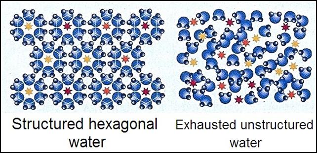
We know from Masaru Emoto's books "The Message of Water" and "The Hidden Wisdom of Water" that structured water has magical powers on our bodies.[2] Its healing power rivals that of soliton waves. So we don't have to wait for someone to reconstruct the Tesla generator, because we can start treating patients on a mass scale right now. All that is needed is to energise the water that comes out of the tap. No expensive equipment is needed, because the ether does it for us. We just need to get to work. A well-known phenomenon in physics is inertia, which is caused by the ether. Aether particles travel across the universe and nothing can stand in their way. They also flood our bodies, but we only notice this when we are driving a vehicle and it suddenly accelerates or slows down. Then we fall backwards or forwards. When we accelerate or decelerate, the dense aether cannot flow into our bodies, so it pushes us like a concrete block. It does the same thing with water, but water has a special property: it can absorb excess energy and retain it for a long time..
 The
presence of etheric energy is not without consequences. The etheric particles
use their energy to eliminate the destructurisation of water resulting from
environmental damage. They create structured water with a regular molecular
structure. This is exactly what the body needs. Many people are on the verge
of dehydration. As we know, we should drink 2.5 litres of water a day to stay healthy. Some people consume a tenth of that. It
is good to drink 1-2 glasses of water
a day. They know they should drink much more than that, but they can't.
They say they don't want water. Their bodies have an instinctive aversion to
destructured, chlorinated tap water. This
situation is radically changed by drinking structured water. The
feedback is that normalising its molecular structure makes tap water soft and
silky, which makes them feel thirsty again and allows them to drink enough
water. Drinking structured water not only eliminates fluid deficiencies in the
body, but also enhances detoxification and nutrient absorption. Structured water has a healing effect on the body.
Over time, it eliminates all our diseases and strengthens our immune system.
It also works wonders in industry and agriculture. Many people have recognised
this beneficial effect and have created many inventions to exploit it. The most
remarkable of these is the invention of a German physicist. This is
also because it can be produced
quickly and very cheaply.
The
presence of etheric energy is not without consequences. The etheric particles
use their energy to eliminate the destructurisation of water resulting from
environmental damage. They create structured water with a regular molecular
structure. This is exactly what the body needs. Many people are on the verge
of dehydration. As we know, we should drink 2.5 litres of water a day to stay healthy. Some people consume a tenth of that. It
is good to drink 1-2 glasses of water
a day. They know they should drink much more than that, but they can't.
They say they don't want water. Their bodies have an instinctive aversion to
destructured, chlorinated tap water. This
situation is radically changed by drinking structured water. The
feedback is that normalising its molecular structure makes tap water soft and
silky, which makes them feel thirsty again and allows them to drink enough
water. Drinking structured water not only eliminates fluid deficiencies in the
body, but also enhances detoxification and nutrient absorption. Structured water has a healing effect on the body.
Over time, it eliminates all our diseases and strengthens our immune system.
It also works wonders in industry and agriculture. Many people have recognised
this beneficial effect and have created many inventions to exploit it. The most
remarkable of these is the invention of a German physicist. This is
also because it can be produced
quickly and very cheaply.
Wilfried Hacheney[3] designed a large device shaped like a lemniscate[4] to release etheric energy particles into water. The water flowing through the horizontal figure-eight tube is forced to change direction constantly, forcing large quantities of ether into it. The lemniscata shape is so effective because every centimetre of this pipe forces the water to change direction. As a result, it constantly bumps into the ether and absorbs a lot of ether ions. Many organic growers use this etheric water to water their plants so that they grow faster. Seeds also germinate better if soaked in this water before sowing. Bread baked in this way will be looser and the dough will rise higher. It has also been observed that concrete mixed with water enriched with ether is stronger than usual.
The efficiency of absorbing the primary energy can be further increased by placing several lemniscates next to or on top of each other. The simplest way to do this is to bend the hot metal pipe into a template and allow it to cool before cutting it into pieces. It is not necessary to fold the ends of the tube by hand, gripping them with pliers, because this task is carried out more precisely by the articulated device[5] used to make the lemniscate. It is thus possible to make a device with up to ten layers, which increases its efficiency by an order of magnitude. Also try to increase the width as long as the technology allows. The wider and the higher the Lemniscata pipe system, the more efficient it is. The pipe snake only needs to be coated with a layer of anti-corrosive anchor and can be used for decades without any problems. (If it is to be buried in the ground or in a pit designed for this purpose, it should be coated with aluminium and at least one layer of oil paint or tar. Also make sure that the top is at least 80 cm below the ground surface to prevent freezing in winter.)[6]
By the way, this method is not entirely new. As early as 1930, Viktor Schauberger developed an energy-enriching device for the artificial production of spring water. The Austrian naturalist used a spiral pipe in which the flowing water is also forced to change direction constantly. However, the efficiency of the spiral shape is much lower than that of the lemniscate. The only advantage of the spiral solution is that by reversing the direction of flow of the pipe or the water, it is possible to produce water that rotates to the right.
Its low-cost production technology makes the lemniscata energy concentrator accessible to anyone. It has no running costs and therefore does not increase the price of the fruit and vegetables it produces. And the cost of purchase is recovered in a few years through an increased yield. In a few years, this equipment could easily become an integral part of every garden or rural household. It could also be easily used by urban water suppliers. All they would have to do is push the water into the hydroglobe bus through a pipe bent into a lemniscata shape rather than a straight pipe, and discharge it through the same kind of pipe. If necessary, an easily bendable plastic tube (rubber or plastic hose) could be used for this purpose. Industrial plants would also benefit greatly from this water, because it would soon become clear that the use of ether-enriched water would not only be beneficial for concrete production, but could have a beneficial effect on almost all products.
The potential for this is already beginning to unfold. For example, similar solutions can save a laundry owner €12,000 a year because less detergent is needed in ether-enriched water. In a riding school in Vienna, horses drink water enriched with ether and are no longer suffering from colic, while in a plastics factory, the use of cooling water has been optimised with the help of special water. Naturopaths have also praised the water. Patients who drink it get rid of eczema, leg swelling and headaches. It seems that the possibilities in this field are also unlimited. The opponents of the method speak of esoteric humbug, but the positive results and enthusiastic reports, which are multiplying day by day, do not prove this. The improvement in water quality and the benefits it brings are visible, tangible and undeniable.
The most virulent opponents of ether-enriched water are the official scientific community. According to academics, there is no scientific explanation for this phenomenon, so they talk of fraud, placebo effect and 'selective perception'. But if every positive result is a figment of the imagination, then overnight we have become gods. We can heal ourselves and others with our thoughts alone, and make effective gains. That would be the real success, because then we could magically solve all the world's problems. Unfortunately, we cannot do that, so for the time being we have to make do with exploiting a physical phenomenon that fortunately works even if the scientific academies refuse to acknowledge it.
In order to avoid disbelief and heated debate, it would be advisable to test this method on a large scale and under official supervision. This would involve designating two blocks of flats in a housing estate or residential area and assessing the health of their occupants. Then a ten-piece lemniscata pipe snake would be installed in front of the inlet pipe of one of the houses. In a year's time, the health assessment should be carried out again in both blocks. After comparing the results, clear conclusi-ons could be drawn about the effectiveness of this method. It would also be worthwhile to install the lemniscata pipeline in a hospital. After a year, it would then be possible to examine how the recovery rate of patients has developed. Whether the length of time patients spend in hospital has decreased and whether the statistics on hospital-acquired infections have improved.
If there is no dramatic improvement, it is due to water pressure. The water company squeezes water into the street pipe network at 6 atmospheres (6 bar) to up to 10-storey tower blocks. Measurements show that this high pressure contributes significantly to the destructuring of the water. In this case, the restructuration should be carried out at the consumer, immediately upstream of the outlet tap. A half- to three-quarter-inch diameter tube containing 10 lemniscats should be placed in a plastic box under the bathroom sink or kitchen sink. The inlet and outlet stubs should be positioned so that they are flush with the bottom of the enclosure. In this way, they can be installed in a recessed position. Covered with tiles, the structure becomes invisible.
 Consumers
of mineral water should not be deprived of the benefits of structured water. To
do this, a 1.5 litre glass bottle with a metal screw cap must be manufactured.
A pipe fitting consisting of 5 to 10 lemniscates is welded onto the top of the
bottle. Both the cap and the quarter-inch diameter tubing should be made of
corrosion-resistant steel. The width of the fitting should not be larger than
the diameter of the bottle or it will not fit in the refrigerator door. It is
also not advisable to make it too high, as this will also prevent it from being
placed in the refrigerator. It is also advisable to make a rubber cap. This can
be used to prevent carbon dioxide from escaping from the 'bubbling' water. The
device is very simple to use. You unscrew the pipe fitting, fill it with
mineral water in a plastic bottle and screw on the metal cap. By tilting the
glass bottle, the water flowing through the lemniscata-shaped fitting will now
flow in a structured way into the cup underneath. The optimum number of
lemniscates can be determined by freezing the outflowing water and examining
its crystal structure under a microscope.
Consumers
of mineral water should not be deprived of the benefits of structured water. To
do this, a 1.5 litre glass bottle with a metal screw cap must be manufactured.
A pipe fitting consisting of 5 to 10 lemniscates is welded onto the top of the
bottle. Both the cap and the quarter-inch diameter tubing should be made of
corrosion-resistant steel. The width of the fitting should not be larger than
the diameter of the bottle or it will not fit in the refrigerator door. It is
also not advisable to make it too high, as this will also prevent it from being
placed in the refrigerator. It is also advisable to make a rubber cap. This can
be used to prevent carbon dioxide from escaping from the 'bubbling' water. The
device is very simple to use. You unscrew the pipe fitting, fill it with
mineral water in a plastic bottle and screw on the metal cap. By tilting the
glass bottle, the water flowing through the lemniscata-shaped fitting will now
flow in a structured way into the cup underneath. The optimum number of
lemniscates can be determined by freezing the outflowing water and examining
its crystal structure under a microscope.
If significant cures are observed with the use of lemniscate piping, this water treatment method should be implemented immediately throughout the country. It would save a great deal of expense to the public health fund, and would also greatly improve the public's sense of well-being and zest for life. This survey is unlikely to meet with resistance from the authorities, because official science says that this method is ineffective. And if it is ineffective, then it can do no harm. If it does, then it makes no difference whether the water enters the building or comes out of the tap through a straight or a tortuous pipe.
Budapest, 23.01.2018.
[
Form radiation
(Functional description)
There are many ways to maintain health, to cure diseases with ether. Most of them do not require expensive investment. As with lemniscate, shape radiation has a low-cost health promoting or healing effect. The only drawback is that its effect is size-dependent. It can only induce rapid healing in large sizes. For the time being, only nature can create a mould radiator several kilometres in diameter. At depths of 10-30 km, the earth's crust is already in a plastic state. If the magma glowing in the interior of the globe can filter this plastic layer in such a way that it becomes convex when viewed from the surface, the shape radiation emitted from it will have a harmonic effect on living organisms. (Not only living organisms but also inanimate objects have an aura. This is called form radiation. Depending on their shape, these radiate beneficial or harmful radiation to living things.)
Beneficial crustal condensation is found in many parts of the world. The most significant in our country is the Attila crustal folds 10 km below the Attila hill in Tapioszentmárton. The energy radiating from the folds, which extend for several kilometres, has made Attila Hill a sacred site. It is named after Attila, the Hun king, who built his wooden palace on this hill on the advice of his shamans. (Our ancestors knew where to build; they were aware of the existence of radiations that could cause illness and those that could heal. Unfortunately, this knowledge has been lost with the advance of modern science. Our scientists have declared the science of their predecessors to be pseudoscience, and forbidden its research.) The rediscovery of this healing area is thanks to the owner of Kincsem Horse Park, who noticed that his horses liked to lie and roll around in a particular part of the property. (Kincsem, the wonder horse, also owes his world-famous winning streak to this energy-boosting magnetic radiation. On his return home, he lay out on the Attila Hill near his stable to recharge. After a few days he recovered and was full of energy for the next race.)
The news of the miraculous cures spread like wildfire, and by the spring of 1999 thousands of people had made pilgrimages to Tápiószentmárton in the hope of being cured. Tourists can sit on the benches laid out or lounge on our blankets on the grass all day. After seeing the great success, the owner of the area decided to investigate the matter, trying to find out the cause of the positive changes using scientific methods. Instrumental tests showed no gamma or other radioactivity. However, the levels of magnetic radiation were very high. According to comparative measurements by Hungarian researchers, while the magnetic balance in Medjugorje and Lourdes was between 50 and 80, the Attila hill had a magnetic balance of over 200. Many of the visitors have seen improvements in their coordination of movement. Those with musculoskeletal complaints have experienced a significant reduction in pain after sitting here for a few hours. Poor la-bor values (e.g. high blood pressure, rapid heart rate, high blood sugar, high cholesterol), which can cause a variety of ailments, also normalised after two to three weeks in the site.
However, these healing places cannot be left indefinitely because they overload the body with positive energy. This also upsets the balance of the meridian system, which can lead to a weakened immune system and infertility. Our ancestors, who were well versed in geomancy, were aware of this. In China, 4000 years ago, an imperial decree forbade the building of dwellings on such a site. Only pagodas, temples and healing sanatoria were allowed to be built on it, where people could stay for a period of time. There are also visitors who do not benefit from the radiation. The reason is that the concentrated etheric waves emanating from the earth only heal those whose illness is due to Yang's lack of energy. It has no effect on other types of energy imbalance.
By the way, most of the patients are suffering from Yang's energy deficiency. The Earth constantly supplies us with Yin gravitational energy, but Yang energy can only be drawn from the ether. This is not very effective and only reaches the desired level in healthy people. Those whose chakras are slowed down, absorbing the surrounding energy with insufficient efficiency, can only access sufficient amounts of positive energy in places with increased space. Subsequently, not only are the diseased organs healed, but the vitality of the patient is increased and the energy available in the previous environment can now supply the Yang energy needs of his body. This, however, requires a full course of treatment, i.e. 10-12 visits or a continuous stay of two weeks. A single trip there will not work wonders, although it will improve well-being considerably. Magnetic radiation also cleans the air. According to measurements taken by the Institute of Radiobiology and Radiation Health on Attila Hill, "the air in the area is extremely clean".
Form radiation can have harmful as well as beneficial effects on the body. In nature, it occurs where the earth's crust is crumpled into a concave shape. Such a highly damaging site is in the Swansea Valley in England. Two English parapsychologists wanted to investigate the healing powers of Corn Leckart in a prehistoric burial site. They stepped into the centre of a circle of stone piles. Unfortunately for them, the circle proved to be harmful rather than healing. Claire Williams felt herself being pushed out of the circle by an unseen force, and Brian Perinton began to suffer from a stomach ache. After they went home, both of them had incessant headaches and gradually became weak. Doctors were unable to determine the cause of the weakness, a major deterioration in well-being.
These symptoms were caused by the disharmonious magnetic radiation of the earth's crust, which upset the energy balance of their meridian system. Our ancestors, thousands of years ago, were perfectly aware of this danger. They warned of this by fencing off the danger area with stones. The two researchers did not know this, so they entered the centre of the circle enclosed by piles of stones. Our ancestors, who lived thousands of years ago, also marked places with harmonic radiation. They used stone pillars with pointed ends to mark them and concentrate the energy emanating from the earth. They healed themselves by leaning against these stone pillars dug into the ground or by staying in an area enclosed by several stone pillars. This was the role played in Europe by kurgans and in our country by kun hillocks. Civilisations more advanced than ours had already made deliberate use of shape radiations and used them to produce a powerful concentrating effect.
The people of the previous civilisation, Atlantis, were perfectly aware of the natural magnetic radiation nature offered them, and this energy permeated almost every aspect of their lives. Atlantis was not yet familiar with electricity. They satisfied their energy needs with form radiation, crystal radiation and a special oreichalcite ore ore (not much is known about oreichalcite, which is more precious than gold). According to ancient writings, its magnetic radiation was so strong that it ionised the air. "It emitted a fiery light." The Greek gods also used this ore. They used it to make destructive ray guns, which they used in their wars with each other.) Unfortunately, this ore is not found on any continent in our world. However, their shape-radiation techniques have survived. These pyramids are found on almost every continent. From China to Europe and North Africa to South America, they built hundreds of huge pyramids in which they hid their knowledge, inscribed on gold plates, so that the coming flood would not wipe out all traces of their existence. (In the Egyptian pyramids, underground chambers containing these documents have already been discovered by ground scanners. We will soon have the opportunity to uncover them.)
But the pyramids were not just for the preservation of knowledge. They were also built to prove their high level of knowledge. So they did not create simple stone mounds, but stone structures that produced a mystical magnetic radiation inside them. The most suitable spatial form for this purpose was the globe. This node, which ends at the apex, is a highly effective shape radiator. When concentrated, it collects the etheric (Yang) radiation that is ubiquitous in the universe, which is most strongly manifested in the lower third of the globe. A cone would do the trick, but the cone is capable of more. If its edges are oriented north-south, it will also collect the gravitational (Yin) radiation emanating from the Earth. This radiation is also strongest in the lower third of the globe. The reason for the precise orientation is that this is where most of the magnetic lines of force intersect the gula. Both radiations are so strong that anyone who lies on a stone slab placed in the third of the sphere not only experiences a strong healing effect, but also activates the organs in his brain (pineal gland, pituitary gland) that cause various parapsychological phenomena.
 |
In a normal environment, such strong shape radiation does not occur. This is part luck, part misfortune. Unlucky because we cannot enjoy the positive effects. Since we don't live in pyramidal buildings, we don't have all the positive effects that the inside of a pyramidal structure has on a living organism. It's lucky, too, because people suffering from energy deficiency would not be able to tolerate this environment in the long term. Headaches, nausea, organ ailments, they would eventually escape. These extremely strong form radiations have a positive effect only on inanimate objects and perishable materials for an unlimited period of time. The sustained Yang energy radiation causes mechanical stresses to be amplified. For example, the edge of a razor blade that has been disfigured will be straightened and sharpened again. The microbes in the food are destroyed. The excess energy overloads their meridians and they become unviable because of the upset energy balance. The beneficial effect for us is therefore the destruction of viruses and bacteria. Concentrated in this form, the strong form radiation is not extinguished but is sustained. However, it does not leave the space bounded by the geometric shape.
In our environment we encounter only weak form radiation. This is the energy radiation emitted by objects of different shapes. As we know, inanimate objects also have an etheric body and thus an aura. Under normal circumstances, this energy radiation is so weak that it has no significant effect on us. There are, however, geometric shapes from which there is a concentrated outpouring of form waves. These include lines crossing at right angles, or edges of different angles in three-dimensional objects, and concave shapes. Magical objects emit a particularly strong radiation. The most famous of these is the "Nile Key" or Ankh cross, found in ancient Egyptian tombs. A similar feature to the cross with ears is the idol resembling the Greek letter "Ф". If a copper or iron ring is fixed to a rod made of the same material, so that the ring is placed symmetrically at the end of the rod, a harmonious device is obtained which neutralises harmful rays. This effect, however, only starts when properly oriented. When worn around the neck or on clothing as a badge, it should be placed with the stem facing downwards. If we use it horizontally (e.g. in our room), it should be oriented so that the stem is pointing directly towards the North Magnetic Pole.
Instead of beneficial, you will get very harmful form waves if you cut the ring in half and assemble this device so that the half circles fit back to back on the rod. In the vicinity of this shape, which resembles the Cyrillic letter „Ж”, we become restless, sleepless and very soon ill. Complex geometric shapes also emit powerful waves of energy. Symmetrical shapes have a positive effect on the equilibrium of the living world, while asymmetrical shapes release harmful energies. The concave mirror is known to collect and focus light rays. Observations have shown that this is also true for magnetic radiation, so avoid staying on the axis of concave objects, and especially not at their focal point.
The aforementioned form of shape radiation that emits harmful waves can only enter the home by accident, through an improperly designed flower holder or other wrought iron ornament. However, a less dangerous but much more common form of damaging radiation source, the cylindrical body, can be found in every household. If they are found in a room in even numbers, their radiation excites each other; if they are in odd numbers, arranged in a row, there is increased excitation. The health-damaging radiation of this nerve agent, which usually takes the form of bottles, jars, pots and pans, becomes really noticeable when a few centimetres of water or other liquids are present. It is not the water that is the problem, as water attracts radiation from the earth, so its presence could be beneficial. The problem is that turbulence develops between the bottom of the liquid in the vessel and the top mirror formed by the liquid surface, causing the water to radiate outwards, amplifying the magnetic radiation it collects.
This radiation is predominantly directed upwards, but if the bottom mirror and the liquid surface are at an angle to each other, the radiation will be oblique. This phenomenon disappears, however, when the half-empty bottle is put to bed. The other solution is to place an object (e.g. a copper ring) in the bottom of the vessel. This breaks the reflective effect of the bottom mirror, which prevents turbulence from forming between the two liquid surfaces. None of this is necessary when the bottle is full. In this case, the contraction of the neck eliminates the upper liquid mirror. This effect does not apply to previously manufactured bottles with a pressed bottom.
Form radiation, also known as idom radiation, is the beneficial or harmful radiation emitted by objects. Form radiation is not the radiation emitted by objects themselves. There are no large objects around us that have significant intrinsic radiation. Compared to the gravitational pull of the Earth, the gravitational radiation of the objects around us can be considered almost zero. Their radiation from their etheric skeletons is also negligible. The bioenergy emitted by living organisms, such as the human body, far exceeds that of inanimate objects. Objects around us can only emit intense energy if they collect it from the environment. We know from the Esoteric Cycle that a wrought iron flower stand placed over a vein of water can itself emit a level of harmful radiation that can make us ill. Form radiation manifests itself in two ways. One is that they emit concentrated bursts of earth, water vein, Hartmann node and other harmful radiation. This happens when a ring sawed in two is welded to the rod of a wrought iron flower holder so that the semicircles fit back-to-back. In this case, the harmful magnetic waves collected by the flower stand are concentrated on the two extensions of the semicircular arches. If these waves are permanently directed towards your chair or bed, you will fall ill even if the source of the harmful radiation is only a few metres away.
The other most common manifestation of shape radiation or nerve radiation is extinction. In the case of a flower stand, this is manifested when a circular ring is attached to the support rod. In this case, the rays collected by the metal structure are not scattered but concentrated inside the annulus, where they cancel each other out. Furniture made in this way therefore neutralises the harmful rays of the environment. The harmful or beneficial effects of shape radiation also depend to a large extent on symmetry. We know from experience that they are amplified in the case of odd-numbered cylindrical bodies and extinguished in the case of even-numbered cylinders. Buildings of asymmetric design also amplify the rays from below, while those of symmetric design largely neutralise them.
This suggests that modern architecture, which favours asymmetrical forms, has also contributed greatly to the rapid increase in diseases affecting humanity. The only reason these effects have not become clear is that they are not always manifest. If there are no harmful radiations in the vicinity of inappropriately designed furnishings or buildings, they are not collected. Therefore, they cannot be emitted. In this case, there is no danger to people in the vicinity. This is why the harmful consequences of design changes, inappropriate trends and fashion trends are not so obvious.
Civilisations outside the Earth have long been aware that angular shapes and intersecting edges block the flow of energy and emit harmful rays. That is why they live in houses with rounded edges, in complexes of buildings that form harmonious shapes. There is no peak, no canting. Their mostly ring-shaped buildings are dome-shaped, dome-covered halls of varying sizes. They are free from harmful radiation, and the pyramidal effect of the dome radiates beneficial energy into the living space. (The dome is not as powerful an energy concentrator as a cone or a cone, so staying under it for long periods of time does not cause overloading of the body. However, it has a significant feel-good and calming effect.)
On their own, these small glands do not have a significant effect on the body. There is, however, a way to multiply their effects. We have seen in the previous work with glass bottles that they amplify each other's radiation when arranged in a row. When using an odd number of bottles, they excite each other. Unfortunately, the literature does not address the question of how far apart the bottles should be placed to maximise the radiation. It would be worth experimenting with this. For esotericists, the increasing radiation from cascaded nodes is not an unknown phenomenon. They have therefore created complex nodes that have a noticeable therapeutic effect on the body.
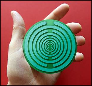
The best-known experimenter was the Russian-French engineer Dr Georges Lakhovsky. Born in 1869, the inventor created a revitalising device called the Multi Wave Oscillator, which is nothing more than a disc the size of the palm of his hand. On this plastic sheet he formed concentric open metal rings that excited each other. The gold metal rings, presumably galvanically deposited, enhanced the excitation efficiency.[7] In the electroplating process, the 24 carat gold is deposited on the object to be coated with high purity, and the purer the material, the more efficiently it can be excited. According to the last great alchemist, the Frenchman Fulcanelli, an atomic bomb can be made from just a few grams of metal and entire cities wiped off the face of the earth. This is possible because "certain geometric arrangements of very pure metals can trigger an atomic explosion without electricity or vacuum". In this case, the explosion is most likely to be triggered by shape radiation. The secret of how this bomb could be made was thankfully not revealed by the hidden 20th century scientist.
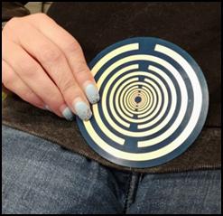
Lakhovsky recommended this 100 mm diameter disc for self-healing. Its operation is based on the principle that concentric rings emit the etheric particles flowing into them in a harmonic form and amplified. This disc, like sacred healing spots, eliminates pain and recharges the depleted body with energy. After Lakhovsky's death in 1942, the patent protection of up to 20 years expired. In fact, more than 70 years after his death, his works are no longer protected by copyright. This situation was exploited by the Serbian Dr. Dino Tomić, who started to produce this disc in large quantities and market it under the name Polaris. This would not have been a bad thing in itself, but his activity was not motivated by altruistic helpfulness, but by the desire to make a quick buck.
 The version he produced is nothing more than a
textile bakelite disc 80 mm in diameter, covered with a thin copper foil. A
common printed circuit board, which is found in all electronic devices. The
components are soldered onto it. Such a single-sided PCB board is produced on a
contract basis by printed circuit board manufacturers for a few hundred
forints. Yet Mr Tomić charges 13 000 for it. Plus a delivery charge of HUF 2
000.[8] He has also removed
the gold plating from the copper foil to make the disc even cheaper to produce.
He prevented the oxidation of the copper foil by painting the disc with light
green lacquer. This significantly reduced its efficiency.
The version he produced is nothing more than a
textile bakelite disc 80 mm in diameter, covered with a thin copper foil. A
common printed circuit board, which is found in all electronic devices. The
components are soldered onto it. Such a single-sided PCB board is produced on a
contract basis by printed circuit board manufacturers for a few hundred
forints. Yet Mr Tomić charges 13 000 for it. Plus a delivery charge of HUF 2
000.[8] He has also removed
the gold plating from the copper foil to make the disc even cheaper to produce.
He prevented the oxidation of the copper foil by painting the disc with light
green lacquer. This significantly reduced its efficiency.
Nevertheless, he sells this reduced-impact device with a profit margin of over 1000 percent. He is thoroughly exploiting the vulnerability of sick people and charging extra profit. He boasts that his remedies are being sold like hot cakes in Germany and America. He has probably sold tens of thousands of them, making a fortune of hundreds of millions of forints. His product is accompanied by a detailed instruction leaflet[9] in which he extols the disc's efficacy for almost every ailment. And on its website, users sing its praises. The problem with these reviews is that they only contain positive testimonials. The negative comments have been omitted, silenced.
We know from blog posts on the internet that even the most perfect products are vilified. If someone catches a faulty one from the factory, he will say everything bad about it, he will badmouth it endlessly. There are no such posts on Mr Tomić's website. He has carefully filtered them out. However, there are some on Facebook, which he cannot remove. Several people have also written that this disc is completely ineffective, just as much a scam as other esoteric gadgets. This is not true. Shape radiation is not a scam, it is just not effective enough in the way it is implemented. This small disc emits a rather weak magnetic radiation. Therefore, to have a noticeable effect on the body, it must be used for at least a month, on a daily basis. The critics had no patience for this. They thought they could just press it a few times on a sore part of their body and be cured.
A remarkable use of form radiators is chakra medicine[10]. Every organ in our body and its cells are supplied with energy by the meridian system. However, the meridians draw their vital bio-energy from the constantly rotating, funnel-like energy centres of our body, through their roots. Thus, if one of our chakras is damaged or constricted, the meridians connected to it will experience an energy deficit. Neither acupuncture nor magnetopressure can deal with this situation. These treatments can only regulate the existing bio-energy, they cannot recharge the meridians. The chakras can only be replenished or dampened by energy radiators. The simplest and cheapest way to passively radiate energy is through form radiation.
The chakras need to be replenished or dampened one by one. Along the spinal column, seven radiating energy fields, seven circles of force, are positioned one above the other like spinning wheels. These centres of life energy are the chakras. At the bottom of the spinal column is the purely subjective, immaterial energy field, reflecting the state before the big bang. The second chakra is the subatomic energy field, which perpetuated the state after the big bang. The third is the atomic energy field, which preserves the beginning of the formation of the material world. The fourth is the molecular energy field, which created the precondition for the beginning of the living world. The fifth energy field is related to cells, the sixth represents the individual organs, while the seventh energy field is the result of the living organism chakra, which is visible and perceptible to all.
The energy centres of our etheric body make up our aura. However, the chakras not only emit energy, but are also very sensitive to the energy radiations of the environment, and even to colours and sounds. So it is no coincidence that different colours and music can affect our health. The root chakra, located on the dam and pointing towards the earth, is sensitive to the colour red and to the lowest note of the musical ladder, the 'c' sound. This energy centre affects physical well-being, vitality and is associated with healing illness, power over other people and sexual energy. The second energy centre is the sacral chakra, which is located below the navel and is associated with the colour orange. Its frequency is the "d" sound. On this centre depends the quality of intellect, spiritual clarity, and the ability to think logically. It affects the process of elimination and purification in the body. The third chakra is located under the breastbone and is often called the solar plexus chakra. Its colour is yellow and its frequency is the "e" sound. This chakra nourishes self-awareness, intuition, general sensitivity and helps to transform gross material into spiritual and mental value.
The fourth energy centre is the heart chakra. It is located on the breastbone, in the line of the nipples. Its colour is green and its frequency is the 'f' sound. The energies of the capacity for love flow through this centre. It is the centre of the joy of life, the chakra of growth, wealth, spiritual and material well-being, but also influences the relationship with the afterlife. The fifth is the laryngeal chakra, which is located in the nape of the neck. Its associated colour is blue and its frequency is the 'g' sound. This energy centre is the sound, the source of expression, the distributor of creative energies. The sixth is the forehead chakra, also called the third eye, because it is located between the two eyes, in the brow line. Its colour is indigo blue and its frequency is the 'a' sound. All manifestations in relation to the spiritual world and man's psychic abilities take place through this centre. The seventh energy centre is the cephalic or crown chakra, located in the cuticle, which is fused after infancy. Its colour is purple and its frequency is the "h" sound. It is through this centre that the cosmic consciousness of total union with etheric energy and God, and of union with the universe, is achieved.
We are alive because our bodies are permeated with life energy. Without life energy we would die within 5 minutes. Our chakras absorb etheric and gravitational energy from our environment and distribute it through our body via the meridians. If this happens evenly, we will be healthy. If the balance is upset by some external influence, we become ill. In such cases, magnetopressure[11] helps by injecting or withdrawing energy to restore the balance (acupuncture only partially helps because it can only inject energy, not withdraw it). Acupuncturists try various tricks, such as silver needles, but these are not effective enough to remove the excess energy.)
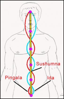
Since magnetic energy flows in a rotating vortex, this is also how the chakras absorb and release the missing or excess energy. Yang radiation has a counterclockwise, i.e. positive, swirling motion, while Yin radiation has a counterclockwise, i.e. positive, swirling motion. The rotational energy of the chakras does not depend on age or gender, their movement is influenced by the body's energy saturation. They rotate clockwise when they take energy in and counterclockwise when they release energy. The chakras are energy centres that are closely interconnected. They are connected to common energy conductors that run along the spine. According to tantra yoga, the ida, which transmits negative (yin) energy, runs along the left side of the spine, and the pingala, which transmits positive (yang) energy, runs along the right side. The Ida carries energy upwards and the pingala carries energy downwards. The two channels do not run parallel, side by side, but intertwine, intertwining like a snake.
In between is the path of the neutral sushumna, on which the yogi raises his physical, mental and spiritual consciousness to ever higher levels through the centres of the swirling chakras. The susumna runs in a straight line along the spinal canal. For ordinary people, the susumna is closed, meaning that no energy flows through it. In this state it resides in the root chakra, coiled up. The sumna and upwards into the brain when the Yin and Yang energies are in complete balance. The ida and pingala are connected to all seven chakras. The ida is charged with Yin energy from the chakras on the back of the body, or the back, while the pingala receives its Yang energy from the chakras on the front of the body.
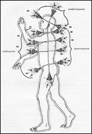
 The chakras depicted in the literature on the thoracic side
do not end at the spine, but have an additional pair on the back of the body.
The opposite chakras are not projections of
each other. They do not collect energy from the front and back in the
same place. The dorsal chakras widen into the same funnel as their anterior
component, but they can function differently. This means that if one thoracic chakra is functioning well, its dorsal
counterpart may still be closed. Although not mentioned in the literature, the chakras on the front of the body
are pingal, the ones on the back are connected to the ida channel. In this way, the front chakras take in and release
Yang energy, while the back chakras release Yin energy. It is common
for the energy in the front chakra to move inwards
normally, i.e. clockwise, but in the back chakra the energy vortex
rotates in the opposite direction. This outward
flow detracts from the beneficial effects of the front chakra or
inhibits the abilities associated with it. It is therefore always advisable to
extend the chakra treatment to the back of the patient. The easiest way to
check the intensity and direction of the energy flow in the chakra is to use a
pendulum. The size of the circle drawn by the pendulum depends on the
strength of the chakra and the amount of energy flowing through it, but is
also influenced by the amount of bio-energy
of the healer. The circular movement follows the direction of the
energy flow. If the movement of the pendulum deviates from a regular circle,
this indicates psychic distortions. If its
displacement is minimal, or if it
does not start circling even when held directly over the skin, it is a
clear sign of chronic constriction of the chakra.
The chakras depicted in the literature on the thoracic side
do not end at the spine, but have an additional pair on the back of the body.
The opposite chakras are not projections of
each other. They do not collect energy from the front and back in the
same place. The dorsal chakras widen into the same funnel as their anterior
component, but they can function differently. This means that if one thoracic chakra is functioning well, its dorsal
counterpart may still be closed. Although not mentioned in the literature, the chakras on the front of the body
are pingal, the ones on the back are connected to the ida channel. In this way, the front chakras take in and release
Yang energy, while the back chakras release Yin energy. It is common
for the energy in the front chakra to move inwards
normally, i.e. clockwise, but in the back chakra the energy vortex
rotates in the opposite direction. This outward
flow detracts from the beneficial effects of the front chakra or
inhibits the abilities associated with it. It is therefore always advisable to
extend the chakra treatment to the back of the patient. The easiest way to
check the intensity and direction of the energy flow in the chakra is to use a
pendulum. The size of the circle drawn by the pendulum depends on the
strength of the chakra and the amount of energy flowing through it, but is
also influenced by the amount of bio-energy
of the healer. The circular movement follows the direction of the
energy flow. If the movement of the pendulum deviates from a regular circle,
this indicates psychic distortions. If its
displacement is minimal, or if it
does not start circling even when held directly over the skin, it is a
clear sign of chronic constriction of the chakra.
The root chakra affects the immune system, the skeleton, and the joints, spine, teeth and gums. The sacral chakra, also known as the abdominal chakra, is responsible for the nervous system, bile, liver and genitals. Its associated organs are the ovaries, breasts, muscles, endocrine system, partially the small intestine and stomach, and the tongue. When blocked, it causes diseases related to the uterus, ovaries, menstruation, testes and prostate. Energy imbalances can also cause impotence, menopausal symptoms, intestinal spasms, gastritis and snow-bladder inflammation. In addition to the stomach and digestive organs, the abdominal chakra condition also affects muscular function.
It is from the navel chakra, also known as the solar plexus chakra, that the will, the passion, the impulse to act decisively, originates. The navel chakra also handles aggression, the fighting spirit. Its disturbance can cause anxiety complaints or outbursts, hysterical attacks, but it is also the source of inferiority complex, sadism and masochism. People with under- or overactive navel chakras often appear uncompassionate, insensitive or ruthless. The organs associated with this chakra are the stomach, pancreas, liver, gall bladder, diaphragm, small intestine and eyes. The heart chakra connects the lower three bodily chakras with the upper three spiritual chakras. It is responsible for the condition of the heart, blood vessels, lungs, skin and hands. It also influences the immune system, affecting the development of allergies, asthma, eczema, cancer and various infections.
The throat chakra affects the ability to speak, hear, write and sing. It also plays an important role in the core hearing and understanding of the 'inner voice' and has an effect on honesty and self-expression. The throat chakra opens the door to the sphere of consciousness and spirit. Over- or underactivity of the chakra most often causes disturbances in speech and communication. The organs of the throat chakra are the neck, mouth, tongue, larynx, vocal cords, oesophagus, trachea. Blockages in the throat chakra can cause hoarseness, sore throat, coughing, ear problems, tonsillitis, asthma, neck pain, tongue problems. The throat chakra can also be blocked by past tribulations, past life shocks.
The forehead chakra or third eye chakra is the centre of intuition, inner perception, cognition, wisdom. The organs associated with this chakra are the brain, face and nose. Its energy imbalance manifests itself in internal tensions, learning disabilities, distractedness, lack of mental clarity and a reticence to learn. Crown chakra blocks can trigger psychic distortions. In addition to neurological disorders, dysfunction can also cause genetic problems and bone and muscle disorders.
Dino Tomić seizes every opportunity to increase his profits. He offers his discs to people on the road who want to heal. For years, he has been advertising his product in a full-page advertisement in the journal Naturist. So many people know about it, but few can afford its horrendous price. The good news is that even those on a budget need not be put off. This disc can be made by DIY enthusiasts. There are no legal obstacles. The original inventor Lakhovsky is long dead, so his invention is now in the public domain. It is no longer protected by patent or copyright. Even if it were patented, there would be no obstacle to production. The patent law allows anyone to make a single copy of any invention for his own use. There is no need to ask for a licence or to pay for it. The patent law only prohibits mass production and commercial sale. This requires a licence from the inventor.
For esoteric inventions, we do not need to count on this obstacle either, because they are not protected. The invention offices will not grant patents for inventions whose operation is based on a physical phenomenon that is not officially recognised. Even if the inventor goes to court, he or she will be rejected, because the judge will ask the Academy of Sciences for its opinion and then declare that, according to the current state of science, the invention cannot exist. And what does not exist cannot be protected. The inventor argues in vain that his invention works. Go out and see! They don't go outside. Those in esotericism are considered impostors, and impostors are not dealt with.
To make one at home, first take a positive film of a foil drawing of one of the discs. (A conventional film camera is required. Since almost everyone nowadays uses a digital camera, this procedure is impractical for many people. However, this problem is easily solved. Take it to your nearest printing company, where they also do contract printing. Book publishers also employ platesetters, because books and colour magazines are now produced from colour-processed film. Once you have the positive film, you get the raw material, the PCB plate. Printed circuit board copper foil textile bakelite sheet is available in DIY stores, handyman shops or order it from web shops[12]. Cut the PCB sheet to size, degrease it with kitchen scouring powder and clean it of oxide film.
Once dry, spray with a light-sensitive varnish. Buy Positive 20 varnish from chemists or web shops. Shake well, then spray evenly over the raw panel in sweeping strokes from a distance of about 30 cm. P20 has a drying time of 24 hours at 20 °C. After drying, lay the positive film on top and illuminate the panel with ultraviolet light. (If it does not lie seamlessly on top, tape the flared edge to the panel with cellux tape.) P20 varnish is sensitive to UV light up to 370-450 nm. Our UV light source can be 12 1 W UV LEDs, or a mercury vapour lamp stripped of its envelope, or a small quartz lamp used for facial tanning. Exposure time is approximately 15 minutes. Do not watch the process because ultraviolet light rays are harmful to the eyes. Do not use a sterilizing germicidal lamp for this purpose, as it is very bright.) Then etch off the excess copper from the textile bakelite plate. (This will leave the copper under the positive film pattern intact, while the illuminated copper will be etched off.)
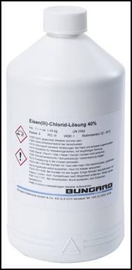
 An aqueous
solution of ferric chloride is used for etching. This brown liquid is available
from chemical stores or online shops.[13]
Pour enough of it into a plastic or glass bowl to cover the plate. Place
the panel so that the copper foil is at the bottom. The etching time can be
reduced slightly by occasionally shaking
the bowl. At this point, it is a good idea to lift it out and see where
the residue is, because if it stays in the bowl any longer, the ferric chloride
will bite into the drawing. You don't need to pour out the ferric chloride
afterwards, because it can be used repeatedly. Reuse only increases the etching
time. The used ferric chloride can also be drained down the drain in a strong
dilution. It is advisable to use rubber gloves when checking the process, but
turning the cuttleboard over with your bare hands will not cause any problems (wash your fingers with plenty of water
afterwards.) Do not start etching in your best clothes, as there is
no way to remove the iron chloride that has dripped on.
An aqueous
solution of ferric chloride is used for etching. This brown liquid is available
from chemical stores or online shops.[13]
Pour enough of it into a plastic or glass bowl to cover the plate. Place
the panel so that the copper foil is at the bottom. The etching time can be
reduced slightly by occasionally shaking
the bowl. At this point, it is a good idea to lift it out and see where
the residue is, because if it stays in the bowl any longer, the ferric chloride
will bite into the drawing. You don't need to pour out the ferric chloride
afterwards, because it can be used repeatedly. Reuse only increases the etching
time. The used ferric chloride can also be drained down the drain in a strong
dilution. It is advisable to use rubber gloves when checking the process, but
turning the cuttleboard over with your bare hands will not cause any problems (wash your fingers with plenty of water
afterwards.) Do not start etching in your best clothes, as there is
no way to remove the iron chloride that has dripped on.
 The easiest way to remove the varnish that protects the
drawing is with household scouring powder. (If you're stubborn, acetone or your
girlfriend or wife's nail varnish remover will wipe it off in no time.) After
it dries, coat the plate with colourless nitrocellulose to prevent the copper foil
from oxidising. If you want a perfect job, take the plate to an electroplating shop where it is electrolytically
coated with 10 micrometres of gold. This version does not need to be coated
with protective varnish because the gold
does not oxidise.) There are several workshops on the Internet that do
this. Ask for a quote. (This process cannot be done in-house.) If you are not a silversmith, you can have this disc made
on a contract basis. There are several
workshops on the Internet that manufacture
PCB discs.[14]
Since no drilling is required,
they will produce this palm-sized panel for us for a few hundred forints.
The easiest way to remove the varnish that protects the
drawing is with household scouring powder. (If you're stubborn, acetone or your
girlfriend or wife's nail varnish remover will wipe it off in no time.) After
it dries, coat the plate with colourless nitrocellulose to prevent the copper foil
from oxidising. If you want a perfect job, take the plate to an electroplating shop where it is electrolytically
coated with 10 micrometres of gold. This version does not need to be coated
with protective varnish because the gold
does not oxidise.) There are several workshops on the Internet that do
this. Ask for a quote. (This process cannot be done in-house.) If you are not a silversmith, you can have this disc made
on a contract basis. There are several
workshops on the Internet that manufacture
PCB discs.[14]
Since no drilling is required,
they will produce this palm-sized panel for us for a few hundred forints.
The way the disc is used is somewhat exaggerated in Mr Tomić's brochure. It says not to use it for more than 5 to 10 minutes at a time, as it causes overloading. It also says that if you do, take a shower and the water will wash the excess energy out of you, just like the crystals. But the reality is that this disc does not cause any overcharging. It's so weak that you can treat yourself for hours without any problems. (Don't sleep on it, though, and don't use it at night.) If you feel any signs of overload, use the disc on the back chakra. Experience has shown that this will draw out the excess energy, eliminating the complaint. Several weeks of treatment are needed to show signs of healing.
For longer periods of time, it is quite tiring to hold the disc against the sore point of the body or the chakras. However, this problem can be easily solved by sticking it to your skin with a sticking plaster. To do this, do not buy the plastic tape that is in fashion these days. These clay-covered adhesive plasters are not waterproof. If they get even a few drops of water on them, they will peel off the skin. They also peel off when the skin sweats. Let's stick with the classic version, the German-made Leukoplast. This is made of a strong rubber smeared on a canvas, which is waterproof. You can even take a shower while using it, it won't come off the skin. However, it is a little problematic to remove because it takes the hair off your skin with it.[15] Glue a few centimetres of Leukoplast to the top and bottom of the disc and press the ends of the disc against your skin. This way, you can work in peace during the treatment because both hands remain free. Alternatively, you can wrap the disc in a thin scarf and secure it with two knots on the other side of your body.
In our fast-paced world, few people have the patience to treat themselves for weeks and see the effect. Instead, they take a pill. But drugs poison the body and cause new diseases as a side effect. But healing with energy (ether ions and gravitons) has no side effects. Moreover, unlike drugs, they do not suppress the symptoms but cure the disease at its roots. Energy medicine is therefore the way of the future. However, this requires effective tools and devices. Passive devices play an important role in this kind of healing because they are mostly small, portable and cheap. However, they are not the most effective. This can be improved through targeted development.
The first step is to increase the size of the disc by a factor of five. Make a disc with a diameter of 80 × 5 = 400 mm. Form 9 × 5 = 45 circular rings on it, in an increasingly wider band going outwards. (It is important that the number of rings is odd, otherwise the radiation will remain inside the disc.[16]) Then we should measure whether the intensity of the radiation has increased. This will be problematic, however, because there is currently no instrument to measure the aether emission. The gravitational radiation can be measured with a gravimeter, but there is no way to measure the strength of the radiation, which consists of aether ions. This is because science denies the existence of aether. And if it doesn't exist, it doesn't need to be measured. Esotericists do have some methods of detecting this kind of radiation (e.g. pendulum, poles), but they are not exact methods. It is quite uncertain and cannot be scaled, it is not possible to express the amount of radiation in numbers or units.
The most reliable tool for measuring magnetic radiation at present is the compass. Approximate a large, bearing-mounted compass to a large disc that can be used for whole-body irradiation. If you are lucky with this size you will already experience some displacement. If not, try a bridge mount. In electronics, the most sensitive instruments are created with two bridge-connected sensor elements. A small difference can be detected in the Wheatstone bridge. In the present case, the difference measurement can be created by placing two large compass needles on top of each other. As the beam source is approached, the tongues of these two compasses will separate or close like a Polish stick. If this instrument is found to be functional, it is then necessary to find out whether the separation and closure are caused by Yin or Yang radiation. (Be prepared for this type of instrument to be affected by the Hartmann node and water ore radiation.)
If neither the gravimeter nor the differential compass shows significant magnetic radiation, try the Egely wheel. Invented and manufactured by mechanical engineer Dr. György Egely, this measuring instrument measures bioenergy radiation. It measures the amount of radiation by the speed of rotation of a special bearing-mounted copper wheel and red-yellow-green LED lights. Detailed information on its operation can be found here: https://www.zotyo.hu/para/egely2.htm and https://mek.oszk.hu/00600/00654/html/kerek.htm It is available at the following address: https://egely.hu/egely-kerek/
The main drawback of the Lakhovsky's medicine disc, or Polaris, is that it is two-dimensional. The circular rings resonate with each other and contact each other laterally with a surface area of max 0,1 mm.[17] It is therefore not surprising that the radiation of the disc is rather weak even when multiplied. This is because extremely thin surfaces oscillate with each other. A significant increase can only be achieved by making this resonator three-dimensional. Lift the circular ring patterns out of the panel plane to increase their lateral radiation by orders of magnitude. This can be done by using copper tubes instead of copper foil. At first try, the length of the copper tubes should be 80 mm.
The drawing of the ground plane should also remain 80 mm. The copper tubes with the walls increasingly thicker towards the outside should be placed on this drawing. The professional version is formed in a white bakelite bowl. (The bakelite is necessary because glass or ceramic will break if dropped.) However, a plain glass jar top is also suitable for experimentation. Pour about 2 mm of araldite resin into the jar and insert the copper tubes from the inside out, following the drawing. Before doing so, slit the copper tubes open. (Use a circular saw to cut a few millimetres wide strips from the casing.) Once the glue has set, take the measurements suggested above. If you are lucky, you will finally experience a noticeable discharge. Brass and bronze tubing cannot be used for this purpose because the zinc and tin used to alloy them are considered contaminants. According to Fulcanelli, only high-purity material can achieve significant mould radiation. Therefore, even if no significant radiation can be measured, the copper tubes should be taken to a galvanising shop and run with gold before soldering. As the gold atoms in the plating bath migrate through the bath to be coated without impurities, this coating is considered to be of high purity.
Afterwards, the tubular mould-radiating device will emit measurable magnetic waves. You also need to measure where the emission is strongest, on the sides or on the top. If it is on the side, it is no longer handheld. The magnetic waves also affect the meridians. Since 3 meridians start from the fingers of the hand and 3 meridians end at the nail bed, these energy lines can be overcharged or discharged. This can trigger various diseases. To avoid this, this device should be placed on a height-adjustable stand and stood in front of it. It can also be placed in a lying position on the chakras, but here several hours of treatment is not allowed. This type of construction is rather expensive because of the high copper price and the gold coating, so it would be advisable to see if it can be constructed from cheaper materials. The cheapest raw material is glass. Get glass tubes of different diameters and wall thicknesses and slice them carefully with a diamond circular saw blade. If you can use glass tubes, you can reduce the production cost by at least an order of magnitude.
For higher volume production, the cut glass tubes can also be produced by pressing. In this case, it would be worth testing the efficiency gains that can be achieved with a completely pure quartz crystal. In the semiconductor industry, the raw material for transistors and microprocessors is produced from high-purity silicon by crystal growth. Single crystal ingots grown by the Czochralski method are extremely clean and free of impurities. These crystal rods are cut into slices, polished to a high gloss and then used to form the circuitry of the microprocessor by photolithography. The material is then carefully inspected and discarded if the slightest damage is found. These broken, damaged rods could be bought up cheaply and melted and moulded. By measuring the device thus produced, it would be possible to verify the truth of Fulcanelli's claim. Does the purity of the raw material really greatly increase the efficiency of the moulding process?
If the 3D mould radiator lives up to its promise, we can start to clarify the working principle. The various claims need to be verified. We need to clear the fog about magnetic radiation. We still don't know whether the beneficial magnetic radiation emanating from the earth is Yang or Yin? Can Yang radiation even flow out of the earth's crust? Is the harmful radiation Yin in nature? According to some esotericists, yes. More sober esotericists explain this phenomenon differently. They believe that only Yin radiation can emanate from the earth. Its usefulness or harmfulness depends on the rotation of the swirling energy. They compare the energy emanating from the earth's crust to water ore radiation. It is said that left-turning water wheels and magnetic vortices are harmful, while right-turning ones are healing.
It would also be good to know what type of form radiation emanating from each object is Yang or Yin? With a sufficiently sensitive instrument, should it also be possible to determine whether the chakras at the front are indeed Yang and those at the back are taking in and giving out Yin energy? Then we would need to find out how magnetic radiation heals. And what does harmful radiation destroy in the body? Does it restore or upset the energy balance of our meridians? Or does it repair or damage the distortions in the etheric body that are transmitted to the physical body? The 28 kHz longitudinal waves used by Tesla probably corrected distortions in the etheric body, which then manifested in the physical body. Psi surgeons, unlike the Filipino healers, do not open up the body, but perform the operation on the etheric body above the body, which is then transferred to the physical body.
This leads to the conclusion that there is a great deal of uncertainty in this field.[18] Almost nothing is known about the world of subatomic energy particles, and we are still in the dark. Extraterrestrial civilisations far more advanced than ours could help us to clear the fog in our minds, but they are in no hurry to enlighten us. It would be good if this uncertainty could be resolved, because until we understand the physical basics, the way esoteric tools and devices work, we cannot develop effectively. Our world is in great trouble in all areas. To get out of the current pit, we need to act quickly. We can only move forward very slowly and bitterly on our own, and we fear that the waves are crashing over our heads.
Budapest, 21.01.2022.
[
In the meantime, the Lakhovsky disc has been tested. At first glance, it looks like a nice piece. It has a fibreglass textile bakelite plate with gold-plated copper foils on both sides. Despite its aesthetic appearance, it is useless as a medicinal disc. It has no effect on the body. It does no good, but it does no harm either. Its ineffectiveness is due to the fact that this disc has an even number of rings (14). Therefore, it does not radiate outwards but inwards. This is also mentioned in the brochure, which states that this 100 mm diameter disc neutralises negative energies (EMF radiation[19], MWO antenna radiation[20]). However, this could be improved by making it three-dimensional. Built as a tube version, this device could be made into an efficient space harmonizer. The larger the diameter and the longer the tubes glued to the base plate, the more intense the effect. Care must be taken here to ensure that the number of rings or tubes is even.
First try to make the medicine disc three-dimensional. This requires an odd number of copper tubes. At first try, this should be 9. The optimum thickness of the tubes and the distance between them should be determined by experimentation. For the initial version, the central tube should have an outer diameter of 6 mm and a wall thickness of 1 mm. This can be sanded with a circular saw blade. A narrow strip should be sawed out of the casing of the tubes placed around it. The width of the strip should be twice the thickness of the pipe. The distance between each tube should be 1,2 times the distance in front of it. The wall thickness of each tube should also be 1,2 times the previous thickness. (A gap of 1,2 mm should therefore be left around the central tube with an external diameter of 6 mm and a wall thickness of 1 mm.) A tube with an internal diameter of 8,5 mm and a wall thickness of 1,2 mm should be glued around this tube, and a strip 2,4 mm wide should be sawed out of its casing. This is followed by a tube with an internal diameter of 14 mm and a wall thickness of 1,5 mm, from the casing of which a strip 3 mm wide is sawed out. The size of the following tubes:
20 mm inside diameter and 1,8 mm wall thickness, from the casing of which a strip 3,6 mm wide is sawed.
27 mm internal diameter and 2,2 mm wall thickness, from the casing of which a strip 4,4 mm wide shall be sawed.
37 mm internal diameter and 2,7 mm wall thickness, from the casing of which a strip 5,4 mm wide shall be sawn.
47 mm internal diameter and 3,3 mm wall thickness, from the casing of which a strip 6,6 mm wide shall be sawn.
60 mm internal diameter and 4,1 mm wall thickness, of which a strip 8,2 mm wide shall be sawn from the casing.
76 mm internal diameter and 4,9 mm wall thickness, from the casing of which a strip 9,8 mm wide shall be sawn.
These are not standard values. Since copper tubes of this size are unlikely to be available, the nearest standard size should be chosen. For example, instead of a tube with an internal diameter of 76 mm and a wall thickness of 4.9 mm, you would have to buy a tube with an internal diameter of 75 mm and a wall thickness of 5 mm. The degree of slippage can also be rounded. In the present case, saw a 10 mm wide strip out of it. The length of the copper tubes should also be a round value, say 80 mm. To prevent the inner rings from leaning on each other before the glue dries, support them. (Put an easily removable plastic or rubber cap on the ends of the tubes.) To avoid symmetry and bending, glue the tubes to the base plate from the outside in. Finally, cover the annular rings. This is necessary because if a metal particle falls between the lamellas, it will create a seal between the annuli. This would have the consequence of reducing the number of tubes by one. This would turn the device into a harmonizer. A cover would also protect the device from dust and dirt. The easiest way to seal it would be to put a white bakelite tray on top of the tubes as well. Pour about 2 mm of two-component araldite resin into it, insert the ends of the tubes and wait for the glue to set.
Once the 3D version is ready, measure the increase in the radiative efficiency. If it is emitting Yin radiation, this can be done with a gravimeter. If it's Yang, you're in trouble, because you don't have the instruments. Our only option is to look for a "seer" who can detect the aura emanating from living and inanimate bodies.[21] From the strength of the emanation, we can deduce the healing power of the device. The "seer" could also help us to know which energy channels are connected to the front and back chakras on our body. It might also be able to determine the direction of the flow of energies in and out of the body. Until these theoretical foundations are clarified, we cannot move forward. If a stronger shape radiator or space harmonizer is needed, try lengthening the copper or glass tubes first. Gilding the copper tubes inside and out before gluing them in place would also be worth a try.
Budapest, 01.02.2022.
![]()
My study entitled Resonance Frequency Excitation revealed that the Keshe generator is not suitable for energy production. Plasma formation cannot be achieved with counter-magnetic excitation, and without it it is impossible to produce a multi-kilowatt free energy generator. However, to increase bioenergy and balance our meridians, a lower power is sufficient, plasma formation is not necessary. Counter-magnetic excitation has been proven to work. It was already used by the Atlantean civilization. The counter-directional winding they sophisticatedly developed was copied by the Mayan Indians and immortalized on a stone tablet. Unfortunately, they could not carve the method of excitation in stone because they could not see it. It was probably in a closed box, behind it. (The photo of it can be found in the description of Resonance Frequency Excitation, together with the other flat coils.)
However, the magnetic radiation of the bifilar flat coil, the counter-directional flat coil and the Atlantean counter-directional flat coil is very weak. It is probably not enough to charge our chakras. Before we discard this solution, let's try it. Let's combine the classic coil of counter-directional magnetic excitation with the Keshe spiral design. In this case, let's create the magnetic radiation source not from a simple copper wire, but from a spiral coil.
Among my scraps, I found an aluminum tube with a diameter of 4 mm and a length of 1.5 m. Since I still had plenty of Ø 0.7 mm enameled copper wire left, I wound it along its entire length. Then, hanging one of its branches about 10 centimeters lower, I carefully folded it in half so that the spiral would not open up. (Not half way, because the outer circle needs a longer length.) Then I wound the two spirals next to each other in a spiral line on a 12 × 12 centimeter plastic sheet. In the meantime, I fixed it with insulating tape in several places so that it would not slip apart. Since the internal resistance of the spiral coil was only 1 Ω, it was not possible to directly excite the coil with the signal generator in this case either. For this purpose, I used the MOSFET amplifier used in the development of Resonant Frequency Excitation.
Now, let's see what the turbocharged counter-directional flat coil is capable of. It did not work with the Keshe generator because the inventor could only use the counter-directional excitation there. This alone is not enough. In order to be sufficiently efficient, the coil must be excited at a resonant frequency. Without this, the snake engine known from ancient legends would not have risen high either. In this bio antigravity drive, the excitation was done by the snake's head. How it was done is not known. Its user only reported that if he placed an iron plate on the snake's head, the vehicle began to fall. Keshe could not excite his coils connected in the opposite direction because the 50 Hz alternating current of the mains current was not sufficient for this. The resonant frequency of the two coils was probably in the kilohertz range.
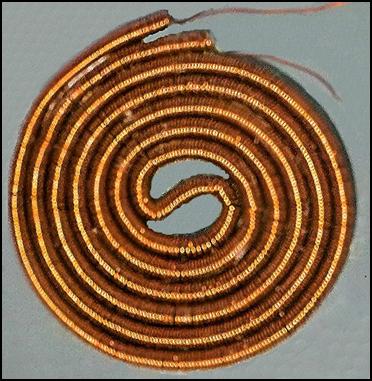 Testing the
finished coil was not easy and raised many questions. After switching on, it
became very hot. Because of this, the
spirals constantly protruded from their
places. I could barely push them back.
The heating is incomprehensible. The cross-section of the Ø 0.7
mm enameled copper wire is 0.5 mm2.
According to the literature, the windings of iron-core transformers
can withstand 2.5 A per square millimeter
without heating. Multiplying the two values, this copper coil should be able to withstand 1.2 A. However,
it heated up already at 0.5 A, and at 1.2 A it caught fire within seconds. At
first I thought that the self-induction current was overheating it. When I
measured it with an oscilloscope, this small air-core
coil produced a self-induction voltage of 70 V at a supply voltage of 12 V. I took out a 30 A Schottky
diode and connected it in the opposite direction to the two inputs of the coil.
The transients stopped, but the diode also started to heat up strongly.[22]
I connected it to this, but I don't know what effect the transients will
have on the purity of the particle radiation.
Testing the
finished coil was not easy and raised many questions. After switching on, it
became very hot. Because of this, the
spirals constantly protruded from their
places. I could barely push them back.
The heating is incomprehensible. The cross-section of the Ø 0.7
mm enameled copper wire is 0.5 mm2.
According to the literature, the windings of iron-core transformers
can withstand 2.5 A per square millimeter
without heating. Multiplying the two values, this copper coil should be able to withstand 1.2 A. However,
it heated up already at 0.5 A, and at 1.2 A it caught fire within seconds. At
first I thought that the self-induction current was overheating it. When I
measured it with an oscilloscope, this small air-core
coil produced a self-induction voltage of 70 V at a supply voltage of 12 V. I took out a 30 A Schottky
diode and connected it in the opposite direction to the two inputs of the coil.
The transients stopped, but the diode also started to heat up strongly.[22]
I connected it to this, but I don't know what effect the transients will
have on the purity of the particle radiation.
Since the self-induction voltage is not heating the coil, I can't think of anything else but the contribution of the ether. As the electrons orbiting the spiral orbit continuously collide with the ether that permeates all matter, a great repulsion occurs in the copper wire. As a result, even more electrons are removed from the outer electron orbits of the copper atoms. Since these excess electrons are not decoupled from the amplifier circuit, they heat the coil. Since this free energy generation is not very large, it is not able to create plasma formation. However, it reduces the excitation current requirement. The easiest way to do this is to reduce the supply voltage.
Due to the strong heating, I was only able to carry out the tests in detail. The first finding was that this coil can be excited in the same way as an electromagnet wound on a permanent magnet. Here too, the excitation with the CMOS wave was the most intense. The square wave with a negative half-period (Square) was not far behind. The sine wave also performed poorly in this case. The step wave (Pos-Ladder) and the exponential wave (Exp-Rise) were somewhat better than it. But only their rising version. Their falling version did nothing. The noise wave (Noise) did the same. It was also possible to establish that this spiral solenoid coil can be excited between 6 Hz and 120 kHz, which is perfectly sufficient for our health protection and healing. Below 6 Hz and above 120 kHz, the MOSFET opened completely and the 8 A power supply shorted out. During the measurements, I set the amplitude of the signal generator to 10 V and the supply voltage was 12 V.
But the big surprise came next. I took out the compass to determine the Yang and Yin surfaces. This is very important, because it does not matter which side we perform the treatment with. According to the literature, a Yang surface emitting etherons:
Ø Increases cellular oxygenation
Ø Attracts fluids and gases
Ø Reduces fluid retention
Ø Promotes deep, restful sleep
Ø Fights infections
Ø Promotes mental acuity
Ø Supports biological healing
Ø Reduces inflammation
Ø Normalizes acid-base balance
Ø Relieves/stops pain
Ø Reduces/dissolves fat deposits
Ø Reduces the dissolution of limescale deposits
In contrast, a Yin surface emitting gravitons:
Ø Reduces cellular oxygenation
Ø Promotes fluid and gas formation
Ø Increases intracellular edema
Ø Stimulates alertness
Ø Accelerates the growth of microorganisms
Ø Inhibits biological healing
Ø Increases inflammation
Ø The pH value becomes more acidic
Ø Increases pain
Ø Promotes fat storage
In the developments with electromagnetics, the compass needle turned towards the coil from a distance of 20 cm, and made wild movements near it. Now it did not move. I put it on top of the spiral coil. Standing steadily in one place, it pointed towards the north corner of my room. It did this when I placed it under the coil. The magnetic excitation in the opposite direction completely extinguished the electromagnetic waves. Therefore, this coil has no Yang and Yin sides. So what should I do now? Etheron radiation, i.e. positive particle radiation, cannot be measured because there is no instrument for it. Now the compass cannot be used for this purpose either. So how should I continue the development?
It is okay that the electromagnetic radiation has ceased, because the bifilar winding also does this. However, the magnetic excitation remains. I took out a coil half-wound with 0.3 mm diameter copper wire and placed it on the spiral coil. It induced. It is true that the amplitude was reduced by a third, but the spiral coil worked. It radiates longitudinal energy from itself, but what kind? Hopefully etherons that have a positive effect. Regardless of this, the other side must be shielded so that the person performing the treatment is not exposed to radiation. Of course, there can be no question of shielding, because neither etherons nor gravitons can be shielded. These energy particles, 12 orders of magnitude smaller than electrons, penetrate all materials like wind through a sieve.
However, they can be insulated. From a greater distance, air is also an insulator. (If we stand under a UFO's engine, we will suffer severe burns and die in a few days. However, if we look at it from 100 meters away, we will be fine.) The development of Resonance Frequency Excitation also revealed that the best insulator is an iron core. Therefore, magnetic waves are not suitable for transformation. Based on this, I placed a 2 mm thick iron plate under the spiral coil. Its backside radiation almost completely disappeared. After that, my science stopped. What should I do with this coil, What is it good for? What can I do with this not very strong radiation?
Theory is missing. Tesla had an easy job, because according to his diary, he got inspiration from the afterlife or from the Venusian civilization. He turned these ideas around in his head, and when he thought it was perfect, he sat down and did it. However, we do not get any inspiration from anywhere. Extraterrestrial civilizations do not help either. We cannot accuse them of indifference, for they have previously told us: “They will not help us because we would turn parascience against ourselves. We would make a weapon out of it and destroy each other with our ray guns.” Their concerns are not unfounded. There are currently several wars going on in our world, which could easily escalate into a world war. Some bloodthirsty politicians are already calling for nuclear war. The unanimous opinion of extraterrestrial civilizations is that our moral development has not kept pace with our technical development.
I would be more happy if some extraterrestrial civilization would give me a primary school physics textbook. After reading this, everything would become clear. However, I am waiting for this in vain. In the absence of this, it would also help a lot if I could develop it together with others. Many people have many good ideas, but no one is willing to cooperate with me. I turn to anyone, and they do not even respond to my letter. I do not receive any financial support, so I cannot hire colleagues for money. So I am forced to continue to struggle alone, and then it will happen somehow.
Budapest, 2025.02.10.
![]()
In the absence of external help, we can only rely on the terrestrial literature. Reviewing and collecting information scattered in various publications is not easy and is quite toothless. The most important information is strictly encrypted and inaccessible. Let us summarize the knowledge available to us. In the case of transverse waves, the energy transfer can be increased by orders of magnitude by using an iron core. The role of the iron core is to transfer the changing magnetic field from the primary coil to the secondary coil as losslessly as possible. Its most important role is to reduce the excitation requirement of such devices, i.e., to create a higher magnetic induction in the device with a given current using an iron core. Another important role is to conduct the magnetic flux. Electromagnetic waves also induce voltage in the iron core, which causes eddy currents. Eddy currents can be reduced by plating the iron core.
The situation is completely different for longitudinal waves created by particle radiation. Longitudinal waves propagate most intensively in a vacuum. In outer space, the flight speed of UFOs equipped with antigravity engines can reach the speed of light. Of course, they never approach this, because at such a speed, even a collision with the smallest particle of dust will punch a hole in the spacecraft's hull. The maximum speed is determined by the tensile strength of the spacecraft's body and the material-deflecting ability of the plasma envelope that forms around it. However, upon entering our atmosphere, the flight speed of extraterrestrial vehicles decreases to 72,000 km/h. As we know, air is a good insulator. It is not by chance that they produce, for example, porous bricks in the construction industry. However, it contains gas molecules that slightly inhibit the propagation of longitudinal waves emanating from the antigravity engine.
Any material that stands in their way reduces their intensity. This is why they can travel at a maximum speed of 1,852 km/h in water, which contains much more molecules (according to the highest value measured so far). In solid materials, they slow down even more. Plastics and other insulating materials already pose serious resistance to longitudinal waves. And the iron core almost completely stops their propagation. Despite this, it does not shield them, because nothing can stop subatomic energy particles that are 12 orders of magnitude smaller than electrons. Similar to gravitons, they rush through all materials like air through a sieve. But only until the material starts to move. At that point, they constantly collide with the atoms of the material, which manifests itself as an inertial force. The same is true if the longitudinal wave pulses and is radiated at different frequencies. In this case, it also collides with the atoms of the material. The material therefore reduces the efficiency of longitudinal waves.
That is why air-core coils are used everywhere to put particle radiation to work. It is no coincidence that Tesla did not use an iron core when creating the coil named after him. Dr. Keshe did not use an iron core in his generator either. He certainly tried this during his experiments, but he realized that this was not the way to go. The longitudinal wave penetrates the iron core, but unlike the transverse wave, it does not induce induction in it, it does not increase the magnetic field strength of the coil on it. (The situation is very similar to bifilar winding. With this winding method, the electromagnetic wave ceases, and the magnetic wave cannot transform.) However, it does induce eddy currents in it, which are not reduced by the lamination of the iron core. As a result, the iron core begins to heat up.
Neither the serpentine drive nor the mercury circulation drive contain an iron core. In fact, they try to minimize the braking effect of air molecules, so the mercury flow flowing in the opposite direction is placed as close to each other as possible. Due to the lack of an iron core and the tight fit, the flat bifilar coil made of copper wire is also very effective. Although counter-current excitation is not capable of producing energy, the etheric radiation emanating from it has a healing effect on the body. The counter-current winding developed by the Atlantean civilization is particularly effective.
This longitudinal wave makes it possible to artificially induce all esoteric phenomena. Raymond Rife's frequency generator operated with concentrated longitudinal waves, which he used to destroy all microbes. A 5-minute magnetic irradiation was also sufficient to cure cancer patients. Concentrated magnetic waves are also needed to make rain and control the weather. The chronovisor, which is based on the detection of longitudinal waves, and the device that allows remote observation also operates using longitudinal waves. Longitudinal signal transmission is also required to communicate with extraterrestrial civilizations hundreds or thousands of light years away.
Let's not rush ahead so much. For now, let's deal with the effect of counter-directional magnetic excitation on health. First, let's try to figure out its mechanism of operation. We already know how to create it, but we are not aware of its operating principle. To find out, I took the small spiral coil out of the amplifier and put it in the Keshe generator. I was afraid that the coil made of thin copper wire would burn out immediately, but the opposite happened. Now I connected 3 100 W incandescent lamps to the output as a load. After switching on, the ammeter showed 1.3 A. I kept it on for many minutes, and after switching it off, I checked the heating of the spiral coil. It did not heat up in the slightest. When excited with a MOSFET amplifier, it heated up strongly at 0.5 A, and at 1.2 A it ignited in seconds. Here it was at room temperature.
From this we can conclude that the reverse magnetic excitation does not produce free energy. This winding method converts electromagnetic waves into longitudinal waves. This offers us a huge opportunity. It will take us from the current electromagnetic world to a new, limitless world. This world was offered to us by Tesla 100 years ago, but we did not claim it. We do not operate the radio with the longitudinal waves invented by Tesla, but with Marconi's method based on electromagnetic waves. With this act, Marconi, in collaboration with the ether-denying scientific community, set back the development of science by 100 years.
This is the reason why we cannot contact extraterrestrial civilizations. This is the result of our space exploration being stuck at the level of 70 years ago. We still launch our astronauts to a height of a few hundred kilometers with Hitler's smoking rockets and beat our chests about how advanced our space exploration is. The extraterrestrials compare our space exploration to the play of kindergarten children. We have only reached the Moon once, while extraterrestrial civilizations travel thousands of light years in seconds. The technology they use is based on longitudinal waves, the propagation speed of which is 12 orders of magnitude faster than the speed of electrons that create electromagnetic waves.
In the counter-current magnetic coil, the excess energy is created by the pulsating excitation current. Its energy-generating effect is greatest at the resonance frequency of the coil. However, the principle of counter-current excitation is not really useful because of the excess energy it generates, but because of its energy-converting effect. This is also responsible for its health-preserving and healing effect. In addition, it has countless beneficial effects on our world. It provides the opportunity to purify the air, purify water, make rain, supply our civilization with free energy, and offers us countless other beneficial effects.
Among others, the anti-gravity effect. Electromagnetic waves are not capable of producing an antigravity effect, although some of them are extremely strong. The world's most powerful magnet, the 25 Tesla induction electromagnet, does not even bounce on the table when the excitation current is turned on. However, it could, because 160,000 A of current is required to excite the electromagnet made at the National High Magnetic Field Laboratory research center at the University of Florida. Since such a current already makes the coil glow, a cooling system containing 13,000 liters of water was connected to cool it. Transverse waves traveling in the transverse direction only exert an attractive or repulsive effect on the opposite poles of their energy source. The north and south sides of permanent magnets cannot be separated from each other either. Therefore, the magnetic waves they emit are also transverse.
Longitudinal waves, on the other hand, have nothing to do with magnetism, although they have an intense effect on the components of electromagnetic waves, e.g. gravitons that create gravitational radiation. Longitudinal waves are created by particle radiation. This particle is nothing more than the ether. It condenses in an electromagnet or permanent magnet. While it is in the material, it is called a magnetic current. Under the influence of the excitation current, the etherons condense in the magnet and emerge from it in the form of particle radiation. The aliens call this radiation “vril”. They form the same wave as gravitational waves, only with opposite charges. Their main characteristic is that, unlike magnets, they do not attract, but repel each other. This is what gives rise to the antigravity effect.
Returning to the original topic, counter-magnetic excitation does not create too large a magnetic current even when operated at a resonant frequency. Spiral winding greatly increased the magnetic current, i.e. the energy radiated from the coil, but this is not enough. More intense radiation would be needed for healing. There are two ways to increase it. One is to increase the size of the coil. With a spiral of double the length, twice the energy could be generated. However, this would result in twice the diameter, which would make it unmanageable. This device will be used hand-held, and a disc larger than 10-12 centimeters cannot be grasped or held in the hand. I found a special method on the Internet to avoid the increase in size. This is nothing more than the coil-in-a-coil method already mentioned in my study Resonance Frequency Excitation. In this version, the two spiral coils are not placed next to each other in a circle, but are built into each other. They make a spiral with a larger and a smaller diameter, and the smaller diameter is inserted into the larger one.
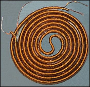 I made a spiral with a smaller diameter from
the same thickness of wire, and inserted it into the spiral with a diameter of
4 mm. It was not easy to make it, because it is difficult to get a thick-walled metal tube with a diameter of 2 mm. Finally, I
found a suitable one in the TEMU online store. I ordered it together with a 4 mm diameter tube.[23] However, no one
sells such thin metal tubes in the required length of 1.5 meters. The longest
size was 500 mm. The only way to make a 1.5 meter long coil with this short
tube is to put another chair next to our chair and gradually lower the finished
coils onto it. Do not hang it on the floor, because the spiral will stretch
and open up. Later it turned out that the 500 millimeter tube is also long for
problem-free winding.
I made a spiral with a smaller diameter from
the same thickness of wire, and inserted it into the spiral with a diameter of
4 mm. It was not easy to make it, because it is difficult to get a thick-walled metal tube with a diameter of 2 mm. Finally, I
found a suitable one in the TEMU online store. I ordered it together with a 4 mm diameter tube.[23] However, no one
sells such thin metal tubes in the required length of 1.5 meters. The longest
size was 500 mm. The only way to make a 1.5 meter long coil with this short
tube is to put another chair next to our chair and gradually lower the finished
coils onto it. Do not hang it on the floor, because the spiral will stretch
and open up. Later it turned out that the 500 millimeter tube is also long for
problem-free winding.
In order to easily remove the threads from the metal tube, saw the 500 mm long tubes in half and deburr both ends. Use 250 mm long tubes. Order the 4 mm outer diameter tube with a 2 mm inner diameter, and the 2 mm outer diameter tube with a 1 mm inner diameter. They should preferably be made of corrosion-resistant steel, because the spiral can be easily slid off their hard, smooth surface. When fully wound, pull off about 4 centimeters of spiral and continue winding on the exposed part.[24]
Since the metal tube as a coil does not rotate here, we have to wrap it with copper wire. In the meantime, it winds like a spiral spring. For this reason, the spool must be lifted frequently and the spirals in it must be removed by rotating it backwards. It is not a good solution to smooth it out with our hands. This will cause the wire to twist. This will cause the enamel insulation to come off and it will tear. This danger is especially prevalent when winding onto a 2-millimeter tube. It will be a much easier thing to do if we care for the wire dosing direction. The wire comes from the spindle in serpentine. Therefore, put it on the floor so that this serpentine smoothes. If you become a spy, set the spindle on top. Also, make sure that the coil being made is pressed tightly against the tube so that it does not turn during winding. This operation is quite tiring for our fingertips, even when using leather gloves. It takes more than a week for the burning sensation to go away. And winding thick wire causes tendonitis. This takes even longer to heal.
However, we only have to endure these torments until the board model is made. If series production is to be carried out, we should look for a transformer manufacturer where robots do the winding. The production of this robot will not be easy. Here, the coil body can only be fixed on one side. The spiral coil continuously flows off it at the other end. The most practical way to design it is to attach a tube made of corrosion-resistant steel about 10 cm long[25] to a low-speed motor, which the robot winds along. Then it stops, a pair of scissors reaches in and pushes a 4 cm long section off. After that, the motor starts and continues winding the freed section of pipe. Then the scissors push another 4 cm off.
The pushed spiral goes into a trough, which must be fixed under the end of the pipe. In this plastic pipe, shaped like a rain gutter, the spiral can rotate freely and does not twist. When it reaches a length of 2.5 m, the worker supervising the robot cuts it off and puts it in a collection box. An additional component is also needed for the robot to function effectively. In order for the coil being made to not rotate on the pipe, the end must be pressed firmly against it. This structure, similar to a brake shoe, must be made of strong plastic (e.g. Danamid) so as not to damage the enamel insulation of the wire. When the motor stops, the brake shoes that clamp on both sides open, and the scissors push the coil off. The brake shoes then close again, the motor starts, and winding continues. The robot can thus produce spiral coils several kilometers long per day.
Leave more than 1.5 meters of wire at the end of the coil. Bend the tip back and tuck it into the larger coil. Then hold the end and gently pull the smaller coil into the larger coil. In the case of series production, you do not always have to throw away 1.5 meters of wire. Make a pull-in cable from 2 mm thick enameled copper wire. Bend the front back and hammer it to 3 mm thick and wide. Hammer the end to 3 mm wide and drill a 1 mm diameter hole in the middle. Thread the end of the 2 mm spiral into this and bend it back. After pulling it through, remove the spiral and the pulling tool can be used again.
This arrangement achieves two things. One is that the counter-magnetic excitation, i.e. the cancellation of electromagnetic waves, becomes even more intense. The other is that the magnetic radiation doubles. It is not easy to coil the double spiral like a snake and place it in a bowl. For the board model, the gluing method is sufficient. Order a 12 cm diameter tile mat from the online stores. (They are made for use as water catchers for houseplants.) Coat the inside with quick-drying glue (e.g. Extrém Pálmatex). (Cyanoacrylate-containing instant glue is not good for this because it dries too quickly. It does not leave time for the threads to align with each other.) Then, wind the two spirals next to each other in a spiral line. Finally, press them down with your palm until the glue dries. If you do not have quick-drying glue, place an 11 cm diameter plate on top and place a few kilograms of weight on top.
In order to successfully complete the operation, it is advisable to follow the following sequence. After making the double spiral, solder the terminal of the outer spiral at one end to the terminal of the inner spiral at the other end, then insulate it with electrical tape.[26] (Scrape off the enamel in a length of about 1 cm, then tin it. Then twist it together and run it with tin as well. Be very careful with professional soldering, because otherwise mysterious errors may occur. Use a high-performance soldering iron, because if the wire does not heat up, the resin flowing from the tin will stick the wires together. This will result in a contact error.) First, file a U-shaped recess in the side of the ceramic bowl with a needle file and insert the rubber cable protector into it. This can only be done with a diamond-dusted file. (Recommended types can be found in the compressed folder.)
Solder the two input wires of the double spiral to the two wires of the connection cable inserted into the rubber cable protector. Insulate this as well. Since there is little space, the rubber cable protector should be between the end of the duplaspiral in the middle. During parallel winding, the ends of the spirals soldered together should be on the outside, and the ends connected to the connecting cable should be on the inside. Then, apply glue to the bottom of the bowl and, holding the two ends of the spiral tightly together, start winding them until you reach the middle of the bowl. There, a loop will form in the middle of the spiral. Press this in the form of a lemniscate as shown in the attached photo. First, apply glue to the bottom of the bowl in just two turns. Press the spiral onto it, and when the glue has dried, continue.
During winding, the spiral may have gaps in some places. We can help this by holding the two ends of the coil and pressing the turns tightly together before pushing a 4-centimeter section off the tube. If it is not closed tightly, we can correct the error now. While gluing, do not only press the threads together, but also press them lengthwise in 2-3 centimeter sections. Eliminate the gaps between the threads. Do this even if the roll has stretched due to insufficiently careful storage. This compression is essential because the spiral, designed for 1.5 meters, will not fit in the bowl when stretched. Since this operation requires a lot of practice, first press the double spiral into the bowl without glue. If it works and fits in, then pick it up and start gluing, then pressing.
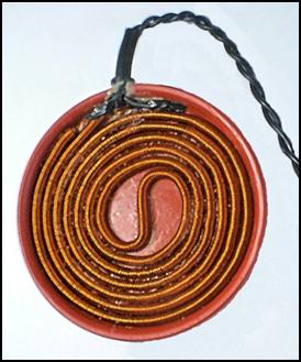 If we want to change the
length or diameter of the spiral, we don't know what size bowl to order. In
this case, a test roll is also needed. This must be done on a plate that holds
the roll together. Self-adhesive paper is not suitable for this purpose
because it will wrinkle. The glue on it is not strong enough to prevent the
roll from falling apart. However, Chinese online stores offer an adhesive tape
that contains 1 mm thick, extremely strong adhesive that prevents the roll from
slipping apart. Nano double side tape can be ordered in 3 cm and 5 cm
widths via AliExpress. Also order a 15×15 cm, 2 mm thick textile
bakelite sheet. Stick 3 strips of the 5 cm wide adhesive tape on it, then
remove the protective film. We can successfully try it on the sticky mass.
If we want to change the
length or diameter of the spiral, we don't know what size bowl to order. In
this case, a test roll is also needed. This must be done on a plate that holds
the roll together. Self-adhesive paper is not suitable for this purpose
because it will wrinkle. The glue on it is not strong enough to prevent the
roll from falling apart. However, Chinese online stores offer an adhesive tape
that contains 1 mm thick, extremely strong adhesive that prevents the roll from
slipping apart. Nano double side tape can be ordered in 3 cm and 5 cm
widths via AliExpress. Also order a 15×15 cm, 2 mm thick textile
bakelite sheet. Stick 3 strips of the 5 cm wide adhesive tape on it, then
remove the protective film. We can successfully try it on the sticky mass.
If the winding is not successful at first, remove the double spiral and start again. (Do not pull the end, because it will stretch. Use your fingernail to scrape the spiral sideways. This will not be easy, because this glue is very sticky. If the work is not urgent, set it aside. This glue dries a lot in a few days and becomes less sticky. If your nails are weak, buy a small plastic spoon from a kitchen supply store.) If you are satisfied with it, measure its diameter and find a bowl for this.
In mass production, it will be easier, because you just have to press the coil into the grooves designed by the toolmaker, similar to the heating element of ceramic stoves. (Start winding at one end of the groove smeared with glue, then lead it back from the middle to the beginning of the coil. When soldering the coil ends together, the inner coil may become slightly shorter, in which case stretch it slightly. (Pull it out further.) If it has become longer, push it into the outer coil. Soldered to the end of the outer coil, it cannot escape. This slipping can be easily avoided if the ends of the outer and inner coils are twisted together before starting winding.
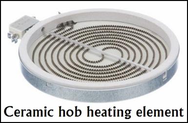 We do not yet know how deep this groove should be.
A 4 mm deep groove makes it extremely easy to place the spiral in the track. In
this case, however, a bakelit wall of at least 1 mm thick is created between
the concentric grooves. The question is whether this insulating layer impairs
the efficiency of the magnetic
radiation. The only way to decide
this is for the tool designer to make a test piece with a 3D printer and
measure it. If it does, it will only be 1.8 mm deep groove can be made,
because this way the coil threads still touch. In this case, you not only have
to glue the grooves, but you also have to hold the coil down until the glue
dries.
We do not yet know how deep this groove should be.
A 4 mm deep groove makes it extremely easy to place the spiral in the track. In
this case, however, a bakelit wall of at least 1 mm thick is created between
the concentric grooves. The question is whether this insulating layer impairs
the efficiency of the magnetic
radiation. The only way to decide
this is for the tool designer to make a test piece with a 3D printer and
measure it. If it does, it will only be 1.8 mm deep groove can be made,
because this way the coil threads still touch. In this case, you not only have
to glue the grooves, but you also have to hold the coil down until the glue
dries.
The bowl in the picture is made of porcelain. However, the coil will not glow here, so porcelain is not needed. However, it will heat up, so it cannot be a thermoplastic. (The melting point of PVC is 160 °C, but it starts to soften at 60 °C.) Make it from white bakelite. (Black bakelite is not good for this because it is colored with soot. And soot contains carbon, which conducts electricity. This can cause a short circuit between the coil threads.) The disadvantage of a clay or earthenware bowl and a ceramic bowl is that it is thick, heavy and fragile. It is worth trying a new type of plastic with white melamine. Melamine is cheap and is sold in several sizes in the AliExpress web store as a dessert plate. Its melting point is 350 °C and it is not brittle. A U-shaped notch must be made on the side, into which the rubber cable protector the power cable of the spiral coil must be pressed. We should not follow the profit-increasing procedure that nowadays electrical appliances are equipped with a 1 meter long power cable. This is not even enough for the amplifier placed on the table or floor to touch the part of our body we want to treat.
For comfortable handling, a 2.5 meter long cable is required. To avoid tearing, its thickness should be at least 3.6 mm. In order for the resistance of the cable not to significantly increase the internal resistance of the double spiral, we order it with a cross-section of AWG 20. (The ideal wire cross-section would be AWG 18, but its outer diameter is already 5.2 mm.) A 2.5 meter long cable is also required to connect the amplifier and square wave generator built into the common box to the mains cable. (In the compressed folder, we find recommended types for all cables, plugs, and sockets. By clicking on the URLs, we can get detailed information about the product parameters on the store's website.)[27]
After the arrival of the AWG 20 cable, it turned out that it could not be used as a connecting cable for the double spiral. When tested, it reduced the intensity of the radiated magnetic wave by 30%. This deficiency can be compensated for by increasing the supply voltage to 12 V, but this causes the spiral to overheat. The resistance of the 5-meter-long AWG 20 cable back and forth is 0.3 Ω, which is comparable to the 2 Ω resistance of the double spiral. An AWG 16 cable is needed here, because its resistance is only 0.1 Ω, which no longer causes a significant reduction in intensity. However, the outer diameter of the AWG 16 double-core cable is already 6.5 mm, which is unmanageable. It is so brittle that it does not fit snugly against the patient's body. This causes hands and feet to get caught in it.
However, there is a workaround. A single-core cable without external insulation must be used. So that it has to be twisted together. A homemade method for this is to fold the 5-meter cable in half and hang it on the door handle, and clamp the two ends in the chuck of an American hand drill or a pistol drill. You only have to rotate the drill for a few seconds to twist the cable together. In the meantime, pull it strongly towards you so that the twist does not unravel after you release it. The twisted cable is extremely flexible. Its flexibility and body-hugging ability can be further increased if you order an ultrasoft cable. This cable consists of tinned copper wires with a diameter of 0.08 mm. Its outer insulation is not PVC, but soft silicone rubber, which improves the flexibility of the cable. [28] However, it is difficult to twist. You will not succeed at first. It is released from the chuck. The operation must be repeated at least twice to keep the braid. However, the two ends are still loosening. This should be tightly wrapped in the converter and the connection plug hand.
The spiral coil is placed in the bakelit sheet so that the rubber cabel protector is located after the two wire ends. There will be enough space here to solder the wires together. (Do not use terminal blocks, car electrical connectors or other screw connections anywhere. Everything must be soldered with these devices!) Strip the end of the connecting cable to a length of about 1 cm and coat it with tin. Scrape the enamel off the two input wires of the double spiral to a length of 1 cm and coat them with tin as well. Then bend them back to a length of about 0.5 cm, then hook the two hooks into each other. Press the wires together with flat pliers, then coat them with tin again. (Due to the strong heat dissipation capacity of the thick wire, a 150 W soldering iron is required.)
Finally, wrap them with insulating tape. This way, the connection will definitely not be lost even if the spiral heats up.) You will also need an approx. 2 mm thick end plate, which must also be made of white bakelite, so that this cap presses down on the spiral coil. Before gluing the cover, apply glue around the rubber cable protector and the end of the connecting cable to prevent it from slipping out of the bowl with frequent use. Use epoxy glue for this.
The amplifier housing should be made of high-quality plastic (polycarbonate). Due to the heat sink heating, a ventilation grille should be provided on the back. The 230 V power connector and the BNC socket of the external signal generator should be placed on the back panel. In order to avoid loosening, it is advisable to use a built-in cable protected by a rubber cable protector. In order to facilitate handling, the mode selection should be solved with a push-button selector switch mounted on the front panel of the box. Glue the inscriptions 28 kHz, 33 kHz and Signal Generator above the push-buttons. It is advisable to put a white plastic cap on the 28 kHz button, a black one on the 33 KHz button and a red one on the signal generator button. The built-in signal generator can also be a cheap square wave generator mounted on a printed circuit board. In these cases, the frequency is adjusted with a potentiometer. We need to measure the resistance corresponding to 28 and 33 kHz and solder these to the toggle switch.
If we want to use a more stable signal generator, we need to persuade a function generator manufacturer to put the CMOS generator on a small printed circuit board and deliver it to us. The Duty should be set to 50% and the Amplitude to 7 V. The other functions are not needed. The JDS2900-15M is the most suitable for external signal generators. It takes up little space and is relatively cheap. In the case of large-scale production, we need to persuade the manufacturer to make it in a single-channel version. TTL inputs, MEAS and SYS buttons are also not needed. By removing the CH2 channel, the OK button can also be omitted. The circuits for these functions should also be removed. This will make it even cheaper and even people without technical training can use it.
Its use is essential if we want to cure diseases caused by various bacteria and viruses. Today, there are tables that provide the resonance frequencies of various microbes. (The American Hulda Clark measured and published the resonance frequencies of hundreds of viruses, bacteria and fungi with the synchrometer she developed. There are many frequency tables on the Internet. The most famous of them is the CAFL list.)
Their use is not always successful, because microorganisms are very creative. When antibiotics are used, they modify their cell walls, which prevents the penetration of drug molecules. This way, they become multi-resistant superbacteria. They cannot prevent the penetration of magnetic waves, but they try. They do this by slightly changing their resonant frequency. Therefore, if we do not succeed the first time, repeat the treatment at a frequency 5-6 kHz higher and lower. (They cannot change their resonant frequency to a greater extent than this.) It may also be necessary to change the frequency because the set resonant frequency depends on the ambient temperature and the aging of the instruments, but most of all on the heating of the spiral coil and MOSFETs. Professional function generators are protected from these changes, but our generator does not have such protection.
The amplifier occupies a central place together with the heat sink. For easier handling, its output should be mounted on the front panel of the device, soldered to a 5.5 mm power supply socket. The power supply plug of the disk-shaped transverse-longitudinal wave converter is connected to it with a 2.5 meter long cable. Exact dimensions can be found in the compressed folder. The illuminated mains power switch of the device should also be placed on the front panel. The timer circuit is also placed in this housing. The 9 V power supply can also be purchased cheapest in the AliExpress online store. Choose between the “board” versions found in the compressed folder. You can also use a version enclosed in a plastic housing. This is not much more expensive either. The 4 A load capacity is also suitable for this.
In the Keshe generator, the coil-in-coil arrangement did not work either, i.e. it did not generate free energy. For this to happen, the coils would have to be excited at a resonant frequency. And for this, 50 Hz was not enough. For this purpose, a 10 kW function generator would have to be developed, the frequency of which can be varied in a wide spectrum. Connecting the Keshe generator to its output would create some free energy. However, the production cost of such a generator would be several hundred thousand forints, which would never be repaid with the low-efficiency Keshe generator.
Let's see what the situation is here. Connecting it to the MOSFET amplifier, the supply current decreased, since the combined resistance of the two coils became 2 Ω. The double coil did not heat up anymore, but the two MOSFET transistors heated up strongly after a few minutes. (This can be eliminated by connecting several transistors in parallel and using a serious heat sink.) Its frequency range extends from 10 Hz to 500 kHz.[29] The waveform used is a positive-range square wave (CMOS). Its current consumption fluctuates, with a 9 V supply voltage and 7 V input amplitude. The fluctuation is quite large, from 60 mA to 1.6 A. This wears out both the MOSFET transistors and the spiral coil. Below 10 kHz, the coil heats up more. At 20 kHz, the heating evens out. Above 30 kHz, the transistors heat up strongly, the coil remains lukewarm. (At 250 kHz, 60 mA flows through the coil, at 25 kHz, 900 mA, while at 10 Hz, 1.6 A flows through the coil.)
This is normal, because the coil heats up for a longer time due to the widening pulse due to the low frequency. It is true that the pause signal also widens, but the coil cannot cool down in such a short time. As the frequency increases, the amplifier's current consumption gradually decreases. Despite this, the MOSFETs heat up more and more. The reason for this is that due to the electron-separating activity of the ether, a much larger current is generated in the coil than it takes from the power supply. This current also loads the transistors. At 250 kHz, for example, the amplifier only takes 60 mA from the power supply. Despite this, the MOSFETs are constantly heating up.
The heating of the transistors can be eliminated by increasing the heat sink. In the last case, up to 10 IRFP4368 type MOSFETs can be connected in parallel[30], which just fit on the 60 × 150 × 25 mm heat sink shown in the Resonance Frequency Excitation appendix. (The soliton wave is very much missing from the signal generators. This makes the work of the free electron separator of the ether even more intense.) An interesting phenomenon is that the coils have several resonance points. At some frequencies, the increase can be sixfold. This is due to the fact that the larger and smaller spiral coils resonate with the solenoid placed on them. It makes no sense to give these frequency values, because they depend on the size of the solenoid and the number of turns of wire wound on it.
Although heating is not bad at 9 V power, the risk of overheating is still there. In order for this medical aid to remain on the whole day, the maximum current should be reduced. In this case, however, the strength of the magnetic wave would be so reduced that it would be difficult to trigger a healing effect. Someone may be treating themselves on a bed. If the overheated spiral rolls fall asleep or the hot transistors light up the device, which causes fire in the apartment. Many have already died in smoke poisoning caused by electrical appliances. It is even more distressing if the careless person is lively enough in the flame-folded house. To avoid this, the amplifier must also be supplemented with a timing circuit[31] that automatically turns off the device after 5 minutes. This is not a problem for treatment, because due to relatively strong magnetic waves, treatment should not take more than 5 minutes. During this time, cancer cells can be destroyed. If you use the device at only 28 kHz and 33 kHz, you will not go down to the Hz range, you can set the timing for 10 minutes. Overheating only occurs at very low and very high frequencies.
The double coil behaved as above assumed. Measured by compass, there was no trace of magnetic poles created by transversal waves. The compass was placed above the coil, placed under and next to the north corner of the globe without shaking. I put on a multi -seated air coil and, by measuring oscilloscope, the magnetic current induced a double amplitude compared to the simple spiral. So a generator emitting a etheric beam has been created, which we do not know for the time being. We can't produce free energy, free current, because it does not emit strong magnetic waves that would ionize the air. This requires plasma formation. However, the magnetic particle radiation is more intense compared to the passive medicin disc on the printed circuit plate.[32] What this is enough is decided by the practical application.
In the meantime, however, a few more things need to be clarified. Previously, I had doubts that the reverse magnetic excitation really emerged from the coil. It may also emit concentrated gravitational waves, which trigger the diseases described above in the body. However, there is little probability because gravitons do not attract electrons or domains. It is true that all materials are permeated, but they do nothing except the hardship (mass attraction). They do not conflict with atoms, they do not separate electrons, or even create a medium resistance. If they did something, it would cause great confusion in the science of electricity. Their neutrality is evidence that the instruments work perfectly in the state of weightlessness. The lack of gravitational waves on the ALFA space base is only a problem for astronauts, not for electrical appliances.
A real problem, however, is that after converting the transversal waves, we cannot measure its strength into longitudinal waves. The compass is no longer working here. In this tight situation, I remembered the invention of Dr. György Egely, the wheel named after him. This small instrument measures the bioenergy that flows from our body. Since this is also a longitudinal wave, it might be able to measure the waves emitted by the spiral coil. However, the problem is that it is very expensive. It costs more than 100 thousand forints, so I can't buy it. That is why I wrote to Dr. György Egely whether he could borrow for a measurement. As usual, he didn't answer my letter now. For the sake of torque, I mentioned that if it worked for this purpose, millions of pieces could be sold from this instrument. This argument did not influence it either.
This device may not be suitable for measuring etheric monopoles. The wheel must be touched close to our fingers. Because of our hands alternating with the starting and endpoints of the yin and yang meridians, the bioenergy between them is measured. Since the spiral coil generator does not have gravitational energy, it cannot measure its radiation. However, the situation is not hopeless. A small frame antenna should be placed 10 cm in front of the spiral and view the amplitude of the induced voltage with an oscilloscope. The unit of voltage 1 v should be 1 vril.
Another solution is to study gravimeter for measuring gravitational waves. This instrument exists and could be used to make a instrument measuring etherons. For now, there is no name for this corrugated coil. What should I call this particle-radiating generator that emits magnetic monopoles and concentrated etherons? Be the name of a magnetic wave generator or magnetic resonance generator? It is interesting to this converter that it does not interfere with the analog radio. There is no radiation of EMF or EMI. This means that it does not produce electrosmog. If we had adopted Tesla's proposal 100 years ago and had launched the development of electronics through longitudinal waves, millions of people worldwide would not have died from strong electromagnetic radiation and would not have received brain tumors from electrosmog.
This generator can be used primarily to increase bioenergy (28 kHz) and to preserve food-free food (33 kHz). When preserving at 33 kHz, be careful. The food to be preserved should not be in a metal container. Unlike microwave ovens, the metal container does not cause a short circuit, it only shields the magnetic waves. More precisely, it does not shield them, because, like gravitons, etherons also rush through the material like wind through a sieve. As already mentioned, the material only insulates the longitudinal waves. The higher the electrical conductivity of the material, the better it insulates. In the case of metal containers made of soft iron or copper, not even 10% of the radiated energy can penetrate them.
This is because the longitudinal wave attracts electrons. Those interested in ufology are familiar with the reports in which if a UFO descends over a car driving on a country road, the car's ignition stops, the headlights and interior lighting go out, and the radio goes silent. The reason for this is that the electrons, obeying the antigravity radiation, gather in one place in the cables. To the point where they will be closest to the strong longitudinal radiation. Because of this, the power supply stops. As the UFO flies away, the car starts, the lights come on, and the radio starts playing again. This is the case here too. The longitudinal wave attracts the large amount of free electrons found in metals with high electrical conductivity, and this binds its energy. (This is probably the case with thick gold and silver plates as well, but I did not have the opportunity to do this experiment.)
Since the maximum frequency of the converter is 500 kHz, it is only limited to healing. (The resonance frequency of the spindleworm in the colon is 580 kHz. The tapeman can not be eradicated because its resonance frequency is 465 kHz.) This requires a halogen -filled gas discharge tube. The gas molecules are much more agile than the free electrons of copper. Therefore, they emit a magnetic wave of the same intensity in their full frequency range. It has a frequency range from 5 Hz to 900 kHz. The most useful product is the joint development of Czech and Slovak engineers, the gas discharge pipe of the RPZ 14 plasma generator. Its detailed description is in my work, Cancer Medicine. It is likely to be ordered separately as a spare part. The method of excitation requires further development.
Budapest, 2025.03.30.
![]()
After the board model has been made and measured, there is nothing left but to test the device in practice. If it holds up in this area as well, then mass production and use can begin. These will not be easy either. Production will be hampered by lack of funds, and distribution by bureaucratic obstacles. It cannot be marketed as a medical device under any circumstances, because it will not be permitted. Officials controlled by the scientific community will immediately pounce on it. They will declare it a scam and a fraud, and will ban its distribution. In addition, they will impose a fine of several million forints on the store. It can only be marketed as a medical aid. However, this is a versatile product.
The field of application of magnetic particle radiation is almost endless. From food preservation to healing to agricultural use, it can be of help in many places. However, to exploit all the possibilities, a stronger beam and greater field strength are needed. I will try this too, but now I have to find out what to do with this little handheld device. Since, unlike the pharmaceutical companies, I don't have billions of dollars, I can't hire poor students to do the tests. For lack of a better word, I was the guinea pig. I tested the effects of longitudinal waves on the body on myself.
One way to heal is to put the converter set to 28 kHz on the painful part of the body. The other is to drink water irradiated with 28 kHz. That's how I started. I put the converter on a glass (2.5 dl) of tap water and left it there for 10 minutes. Then I drank it. I didn't feel anything. It tasted the same as untreated tap water. I used to drink Pi water regularly. (The Life Energy device that produces Pi water was patented by Dr. Soji Jamasleita in 1983.) Tap water first passes through a pre-filter that filters out suspended impurities. Then it goes through three more filters. In the first stage, an active filter filters out odor-causing gases, turbidity, rust, and chlorine that has entered the tap water. In the second stage, there is an IMS ceramic filter that filters out remaining impurities while stabilizing the alkalinity and acidity of the water. In the third stage, the water passes through an active lime filter that gives it a taste similar to natural spring water and stabilizes its hardness.
Then, the two-stage activation begins. First, the sufficiently filtered water is pre-activated by flowing along the mantle, and then enters a section containing strong permanent magnets, where it is energetically charged by the Yang poles radiating subatomic energy. Before leaving the device through a throat tube, it also flows through a BCS ceramic filter, which neutralizes the harmful effects of eddy current energies and ionization phenomena resulting from magnetization. The Pi water, also known as the water of life, created in this way is very clean, has a much more pleasant taste than tap water, and only after tasting it does one realize what they have been drinking with it as drinking water until now. Anyone who has once tasted this smooth-tasting refreshing water will no longer be able to drink heavily chlorinated tap water containing various impurities.
In addition to its medicinal and other effects, the domestic use of Pi water also has significant advantages. Due to the germicidal properties of the water of life, any food that is mixed with Pi water can be kept for much longer than if ordinary tap water were used. Foods containing Pi water can be stored well at room temperature, and do not need to be refrigerated. The water of life retains a significant part of its energy even during heat treatment. Therefore, anyone who uses Pi water for cooking will benefit from all the healing effects that can be achieved by consuming the water of life on its own. Pi water also plays an invaluable role in preservation, as vegetables and fruits that are poured with it and sealed airtight do not usually need to be heat treated, this is done by the energy radiating from it. This does not damage the vitamin and enzyme content of the raw material, so we do not have to worry about any health damage when consuming these canned goods.
Unprocessed agricultural products (e.g. apples, pears) can also be stored much longer if washed in Pi water before storing for the winter. Vegetables and fruits that spoil quickly can also be stored for a long time if soaked in a container filled with Pi water for a few hours. Another special property of Pi water is that it preserves the vitamin content of the vegetables cooked in it during cooking. After 5 minutes of boiling, not a single milligram of vitamin can be found in a vegetable soup. However, when cooked in Pi water, a quarter of the vitamin C content of the vegetable is retained. Therefore, those who cook or steam vegetables and fruits in Pi water will be less exposed to diseases caused by vitamin deficiency. Incidentally, cakes made with the water of life will also be looser, tastier, and rise higher. Bakers also bake more beautiful and tastier bread from dough made with Pi water.
Pi water is not only beneficial in the kitchen. It brings us almost inestimable benefits in agriculture. When used as irrigation water, the yield increases by almost 30%, the crop develops faster and becomes more beautiful than on fields treated with artificial fertilizers. Incidentally, the life-giving effect of rainwater can also be attributed to the fact that etheric energy particles are trapped in the raindrops falling at high speed, which are absorbed into the plant together with the water. Therefore, irrigation water cannot replace rainwater, although tap water also contains nutrient salts, while rainwater is actually distilled water. In addition, in addition to the yield of plants treated with pi water, their drought tolerance also increases, which is a significant advantage considering the current drought.
Another special feature of this process is that the fields washed with the “water of life” will not require any nutrient solutions in addition to chemicals, and yet the soil will not be depleted. The plants will synthesize the mineral salts they need from subatomic energy particles. This phenomenon can already be observed today among the Inedians, that is, people who have not taken in either food or water for years, yet enjoy excellent health. During the experiments, Dr. Lin’s studies showed that the sugar content of the fruit in the melon fields irrigated with the treated water increased from 11.74% to 14.14%, and the size of the melons also became larger. However, the most striking change was observed in the structure of the plants. The foliage of the treated water specimens appeared darker in color, healthier, brighter, and showed fewer signs of aging. The exportable yield increased from 34.1% to 56.7%. The treatment increases the solubility of water and eliminates scale and algae growth in irrigation pipes.
In Immokalee, Florida, Dr. Everett conducted experiments on the Sunny outdoor tomato variety. He drip-irrigated the plants, which were planted in raised beds covered with foil, with magnetically treated water. Even more surprising than the 12.5% increase in yield was the discovery that the treated water plants had less sulfur, manganese, copper, and zinc in their leaves, and lower concentrations of phosphorus, magnesium, calcium, potassium, copper, manganese, and zinc in their fruit; but adequate amounts of each nutrient were available. A pomegranate plantation – which was also irrigated with magnetically treated water – used half the amount of fertilizer compared to the previous ones, yet achieved a record yield. In addition, the harvest was able to start two weeks earlier than in previous years.
The most effective way of chemical-free crop production will be the use of Pi water. In addition to making fertilizer unnecessary, water treated with subatomic energy keeps insects, viruses and fungi away from the plants with its radiation. Based on previous experiments, at least a twofold increase in average yield is expected when seeds are irradiated with concentrated energy before sowing. In order to prevent frost damage, pre-germination of seeds with subatomic energy will become a common practice, which will also allow the sowing time to be postponed. By using this method, agricultural crops will be moved further north, and vegetable and grain production will be possible in areas where summer lasts only 1-2 months.
In addition, this liquid also has a preservative effect, since vegetables and fruits treated with Pi water begin to deteriorate much later than usual. The use of “living water” also has significant benefits in animal husbandry, since the same weight gain can be achieved with 25% less feed, and the egg-laying period of poultry can be doubled. In addition, this water repels flies from the vicinity of livestock farms and greatly improves the condition of the soil. Pi water neutralizes chemicals that have entered the soil, so that earthworms reappear and the original, natural state of the poisoned soil is soon restored. (This water also has a special effect on aquatic animals. If goldfish are placed in a closed aquarium, they will die within 24 hours. On the other hand, if the pool is filled with "living water", the fish will still be swimming happily in it after 1 day. It is strange that fish that are born in this water enriched with subatomic energy will die immediately if placed in a tank of normal water.)
In the future, famine will also end, and this will not only be due to the increase in average yields and the geographical expansion of agricultural crops, but also to the long-term shelf life and loss-free transportability of the produced food. Taking advantage of the bactericidal effect of concentrated subatomic energy radiation, foods that are not directly used will be treated with energy before storage, thereby minimizing the risk of spoilage. Canned goods will then not be preserved with carcinogenic chemicals or vitamin-damaging heat treatment, but will be made fresh and tasty for a long time with energy irradiation. The enzymes that promote the absorption of minerals will not be destroyed either. In the field of preserving food products, this new sterilization method will be of great importance, especially in the dairy industry, since the pasteurization currently used greatly damages the vitamins in milk and destroys its enzyme content. (In the absence of enzymes, the calcium content of milk is not incorporated into the bones, but is deposited on the bones, which sooner or later causes rheumatism.)
Irradiation sterilization is already used today both in the food industry and in the production of medical devices, e.g. to sterilize injection needles. At present, however, sterilization is carried out with a radioactive radiation source, which makes the procedure very expensive. The huge cost arises, on the one hand, from the high price of the cobalt gun that produces gamma rays, and on the other hand, from the forced use of safety equipment that protects the operating personnel from harmful radioactive rays. Since subatomic energy irradiation does not have such disadvantages, nothing will prevent the widespread spread of this preservation method.
Moreover, unlike radioactive radiation, preserved food does not produce hydrocarbons or free radicals that cause cancer, atherosclerosis, and premature aging. In addition, irradiated food becomes biologically dead. A clear proof of this is that potatoes, garlic, and onions treated with gamma rays do not germinate. This has been considered an additional benefit by food distributors, but we pay the price for this with health damage. However, concentrated magnetic radiation does not destroy cells, does not render sterilized food lifeless.
Since the development and editing of my books require a lot of time, I can't devote myself intensively to testing the magnetic wave generator for the time being. I just did one experiment. After baking bread at home for years, I thought I would test the effect of magnetized water on it. I subjected the water to be added to the sourdough and dough to 10 minutes of radiation. The result surprised me. The baked bread became higher and tastier than before. The biggest surprise was that I could smell the delicious smell of baking bread again. Nowadays, hybridized wheats grown on heavily chemicalized soil have no taste at all. The biggest problem is that bakers use flour with additives. Mills mix dozens of chemicals into it so that the bread baked from it rises faster, does not crumble, and does not mold. This gives it such a chemical taste that it makes your mouth water.
In many countries, the situation is aggravated by wheat grown using GMO technology. When I was a child, bread was baked from Bánkúti-1201 wheat. It had an unforgettable taste and smell. Then in 1972, hybrid wheat varieties were imported from the Soviet Union on the grounds that they had a higher yield. However, their gluten content was far below that of Bánkúti wheat, which had a gluten content of 43%. Flat, tasteless bread could be baked from them. This is why home-baking of bread ceased in the countryside. The pursuit of profit does not allow maintaining quality. Even the Alföld-90 wheat variety, hybridized from Bánkúti wheat, could not change this situation, because it did not produce enough either. Then people got used to tasteless bread. Two generations grew up who had never even heard of what real bread was like. The situation was further aggravated by the fact that supermarkets also degraded the texture of tasteless pastries. Their locally baked products are baked at high temperatures because their electric ovens use less electricity. They look deliciously browned on the outside, but they are raw and undercooked on the inside. And for me, lunch that day was a fresh, crispy sandwich made with potato Graham bread.[33]
According to medical research conducted in Japan, energized water also has a healing effect. Patients suffering from diabetes at the Suzuki International Medicien Clinic received 3×10 drops of concentrated Pi water daily. Most of them were able to significantly reduce their insulin doses within a year. Some of the patients participating in the experiment were over 70 years old and had been insulin-dependent for more than 10 years. Some of the patients treated with Pi water for 6-8 months did not require insulin injections. Regular consumption of the “water of life” has cured many people of stomach ulcers and diabetes, but it is also useful for indigestion, rheumatic pains, heart problems, edema, leg ulcers, nephritis, kidney stones, hepatitis, high blood pressure, gallstones, herpes and various skin diseases, influenza, migraines, insomnia, impotence, and even hair loss. Its most significant effect is that it can also regrow cancerous tumors.
However, the diseases just listed are only isolated cases, as new examples of application are heard every week where Pi water has also helped. There are many, for example, who use this water to quickly heal bruises or open wounds, because it enhances sprouting, but healthy people also drink it in order to increase their vitality and mental concentration, as well as their stress tolerance. It is even good for cosmetic purposes, as it enhances the penetration of various active ingredients into the skin, and regular consumption eliminates stretch marks.
Thanks to the blood-purifying effect of Pi water, those who use it for a long time will give up eating meat, because their body will increasingly accept biologically impure, poisoned food. It is equally beneficial for smokers, alcoholics, and strong coffee addicts. For people struggling with harmful addictions, regular consumption of Pi water almost by elemental force forces them to switch to a healthy lifestyle and diet.
It is well known in esoteric literature that the brain frequency of animals is stuck at the alpha level, which is why they react very sensitively to subatomic energy radiation. Based on this, Pi water will easily solve the problem of keeping them away from unwanted places. In agriculture, for example, expensive wildlife fences and fairly inefficient scarecrows will no longer be needed. It will be enough to irrigate the area to be protected with Pi water, and from then on, wild animals and birds will avoid the area in a big way. Since the subatomic energy is also absorbed in the soil, it will also solve the problem of rodent control in agriculturally utilized land.
This will not adversely affect the quality of the soil, because earthworms are particularly fond of subatomic radiation, so they will continue to perform their soil-decomposing task. Rodent control will also contribute significantly to the eradication of hunger. Crops are destroyed not only by field but also by urban rodents. There are currently ten times as many rats on Earth as there are people. In Indonesia, rats eat about 15% of the rice crop. With this amount alone, 20 million people could live well for a whole year. In addition, Pi water can be used effectively in many other areas, e.g. in wastewater treatment, in the regeneration of lake and river water, in the desalination of seawater, in the food industry to replace preservatives, or in the production of anti-corrosion, deionization varnishes in the paint industry.
The magnetic wave generator will make it easy to scare birds away from airplanes and airports. This method can also be used to protect monuments. By the way, in Paris, they have already started building a system based on a similar principle. First, they installed an electromagnetic alarm on the Louvre building, and they were very satisfied with the result. After that, they freed the expensive boutiques and restaurants under the arcades of the Palais Royal from pigeons. Previously, they could not use any means to prevent them from building nests in the arches. Now they are not even willing to rest nearby, let alone settle down. However, the disadvantage of this primitive system is that its installation is very expensive. Another disadvantage of thin wires powered by weak current is that they emit Yin and Yang rays at the same time, so the efficiency is not very high, and the appearance of buildings and statues woven with wires is not exactly aesthetic. The concentrated radiation source, however, is free from this disadvantage, and its price will be so low that many people will use it in their homes to drive away mice, rats, cockroaches, bedbugs, spiders, moths, ants, mites, and to keep mosquitoes and flies away.
However, this very advantageous situation from a health perspective will have a downside. The subatomic radiation source will not only drive away rodents and insects, but will also drive the pets kept in the neighborhood crazy and make them flee. Therefore, a conflict will arise between dog and other pet owners and citizens who want to get rid of harmful parasites, which will have to be resolved by legislation. This will not be easy, because dogs and cats now play the role of children in most families. Their original function (guarding the house, catching mice) is now only performed in the countryside. If you don't have or can't have children, you adopt a dog or a cat. Then you treat it accordingly. You pamper it for the rest of its life, and when it passes away, you mourn it. In the past, animals become a carcass, but now they die. After their death, they were thrown into the garbage dump. Today, they are buried in coffins. It's a good thing they don't invite a priest to the ceremony. It's typical of our emotional behavior, of our upside-down value system, that even in the news today, animals don't become a carcass, but die.
In the Life Energy device, the water is magnetized by supermagnets with their Yang side turned inward (probably neodymium or samarium-cobalt magnets). Since the water passes through them in a few tenths of a second, they can't absorb nearly as much magnetic energy as the frequency generators give. The magnetic wave generator radiates etherons into the water with an amplitude of at least 40 V for 10 minutes, which causes a magnetic saturation that is at least an order of magnitude higher than that of permanent magnets. Therefore, the preservative and healing effects listed above will be more effective. However, testing these would require the cooperation of the entire population. I do what I can in the household, but I do not have the opportunity to conduct agricultural trials. I do not have a garden or agricultural land, the completion of these experiments is waiting for others. All I can do in this area is to collect the information that comes to me and publish it regularly.
By the way, magnetic therapy is not a new thing. Most of the devices currently on the market contain electromagnets, which are not exactly ideal radiation sources. Despite this, it is also useful. They are mainly used for healing. They reduce inflammation and improve circulation by acting on cells and receptors. They increase cell metabolism and tissue regeneration. They improve mobility and reduce pain. Magnetic therapy affects the nerve fibers that conduct pain. Due to its cell renewal effect, pulsed magnetic therapy can also be used as an additional treatment for osteoporosis. It supports Parkinson's disease and multiple sclerosis therapy. It can also be used after recent injuries and operations. However, its use should be avoided near pacemakers and in pregnant women.
Since esotericism is an almost completely unknown field for the average person, dozens of scammers have appeared in this field. They sell their customers with highly praised ineffective products, at exorbitant prices. Flat magnets sewn into pillows, duvets, and sheets, relying on the healing power of static magnets, appear. Most of them are completely ineffective because the magnetic tiles are thrown in indiscriminately. They don't care about their polarity. That's why one faces up and the other down. So one benefits, the other worsens our condition. Fortunately, they put in quite weak magnets, so no one dies from the wrong treatment. There is only trouble if one of the magnets is placed over an acupuncture point. If we lie on the saturated point of the bladder meridian on our waist, then in the morning we get such lumbago due to the overload that we can barely get up. Lumbago caused by energy overload is a very unpleasant disease, because it takes up to a week to go away. (Magnetopressure can speed up the healing process and remove excess energy.)[34]
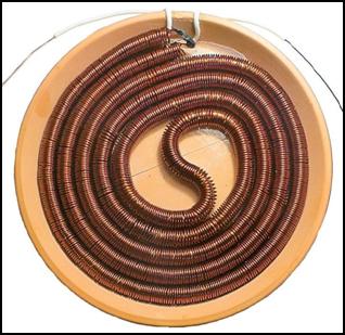 After the
long theory, let's get back to the development and further development. Since
the field strength of this small handheld device is not very high, I thought
that we should make a sled structure on wheels, which could be pushed over the
patient's bed and used to cure cancer patients. The "little grays"[35]
from the planet Quintumnia, 68 light years away, gave a demonstration,
where they eradicated metastatic cancer cells from an American woman in the
final stages of cancer in a few minutes. According to the woman's report, they
dragged a sled back and forth over her body, which had several small radiation
sources on it. I thought we could make something like that too. I would place 9
converters next to each other or under each other, which would increase the
radiated energy ninefold. Then I also thought of how the whole body could be
irradiated with life-giving energy. To do
this, 9 converters would have to be mounted on a column. In order for
several people to be able to charge themselves with energy at the same time, an oscillating column would have to be made.
(There is a small motor at the base of this, which rotates the column at an
angle of 90° to the right and left. Modern
fans and radiators are now equipped with such a motor.)
After the
long theory, let's get back to the development and further development. Since
the field strength of this small handheld device is not very high, I thought
that we should make a sled structure on wheels, which could be pushed over the
patient's bed and used to cure cancer patients. The "little grays"[35]
from the planet Quintumnia, 68 light years away, gave a demonstration,
where they eradicated metastatic cancer cells from an American woman in the
final stages of cancer in a few minutes. According to the woman's report, they
dragged a sled back and forth over her body, which had several small radiation
sources on it. I thought we could make something like that too. I would place 9
converters next to each other or under each other, which would increase the
radiated energy ninefold. Then I also thought of how the whole body could be
irradiated with life-giving energy. To do
this, 9 converters would have to be mounted on a column. In order for
several people to be able to charge themselves with energy at the same time, an oscillating column would have to be made.
(There is a small motor at the base of this, which rotates the column at an
angle of 90° to the right and left. Modern
fans and radiators are now equipped with such a motor.)
Since these converters do not need to be held in the hand, they could be larger. Thicker wire would withstand heating better. Theoretically, the resistance would not decrease either. It is true that thicker wire has lower resistance, but the diameter of the double spiral is larger. This would make the wire longer, which would not increase the current flowing through the coil. I thought I would not waste it, I would immediately double the wire diameter. I ordered 1.6 kg of 1.5 mm diameter double (enamel + varnish) insulated copper wire from the Hungarian web store Zotek. (They have the cheapest one.) I wound the 2.5 m long outer spiral on a 15 mm metal tube, while the inner spiral was wound on a 9 mm diameter metal tube. For their opposite winding, a 24 cm diameter and 5 mm thick bowl is required. Since I do not yet have a bakelite bowl of this size, I used a clay bowl with an outer diameter of 28 cm, made for flower pots, instead.
The measurement did not turn out as I had hoped. The current flowing through the large-diameter double spiral coil did not exceed the current of the small spiral wound from a wire with a diameter of 0.7 mm, but the radiated energy hardly increased. The 70 V spikes of the small coil increased to only 80 V here. However, it did not heat up in the slightest.[36] However, it did not heat the slightest. Well, this is not a great increase in the signal strength. If the force of the coil with an eight-time mass of copper increases by only 15%, it is not a great success. However, this situation cannot be radically changed. As it has been mentioned, the self -induction voltage does not increase by increasing the supply voltage. Unlike coils excited by transverse waves, increasing the number of threads here does not increase the voltage.
The only way to increase the signal strength is to reduce internal resistance. There are two ways. One is to increase wire thickness, which is usually accompanied by an increase in the spiral diameter to reduce the effort of the winding. The advantage is that the thicker the wire, the less warming the coil. Another way to wrap a shorter spiral. However, it is not possible to reduce it too much, because if the number of sideways side-by-side is less than 3 in a snake-like flat coil, the reverse magnetic excitation will not be created with satisfactory efficiency. We cannot fully get rid of the transversal waves.
The common disadvantage of both solutions is that reducing the double spiral resistance increases the current flowing through it. This is not a problem when increasing wire thickness, but this larger current flows through MOSFETs, which heats it more and more. While the heat tolerance of the transistors can be increased by screwing 10 pieces MOSFETs on a palm sized heat sink, but a fan cooling should be applied above a certain limit, which should be avoided in many ways. A high-performance power amplifier stage that does not require excessive cooling would be needed. There are so many, but almost all of them are audio end enhancers. However, the more powerful people are cooled here with a fan. I looked around the internet to see if there was a solution.
I found a promising amplifier. The Chinese Miboxer company sells a 25 A amplifier in a flat cube of 6 × 8 centimeters for just $ 4. This is a unit that controls LED garlands. I tried to get up with them. To my great surprise, they answered my letter. They sent a quote that, when buying 100 pieces, their PA1 amplifier costs only $ 3.5. At the same time, they were asked what this device needed for me, what would I connect to it. I told them I would like to create a high -performance signal generator, with an outgoing current not 250 mA but 25 A. Instead of 1 Hz to 15 MHz, 10 Hz - 900 kHz is a frequency range. I also wrote that I need a 50 Ω outgoing resistance space for 1 Ω, but it is no problem to fulfill this, because grounded collector switchings know it. This task seems to have exceeded their abilities because I didn't get an answer to this letter. This way, there is nothing more than ordering a 150 mm long heat sink in the compressed folder and ordering 10 pieces 350 Amper MOSFET.
I also have theoretical problems with this invention, if at all, this device can be called an invention. During my recent measurements, it became clear that this converter is actually nothing more than an induction generator. In terms of operation, it differs from ordinary electromagnets in that it does not emit transverse waves. I turned off the converter from the amplifier and tied the solenoid. This did not cause overload because their internal resistance was roughly the same. Because of this, he behaved in the same way as the converter. His self-induction spikes also ran to 80 V. The only difference was its radiance. I took out the compass and examined it. The compass attracted the black and the white tip. That is, he behaved as expected from an electromagnet. It was a transversal force. I replaced the converter. I checked this again too. Neither on the side, on the top or on the bottom, the compass was modified.
So this is a roll -free roll that I can't do with. I don't even claim to emit longitudinal waves because I can't measure it. I don't even know what to measure, because I measure particle radiation. You should try what this device can be used for. However, I need thousands of contributors to carry out medical and agricultural experiments, but no one is willing to help. For the time being, all I can do is transfer this large -diameter double spiral converter to the development of the Resonant frequency generator and try to revive the impossible, the Keshe generator. However, I would need money for these developments because all my reserves have run out.
Budapest, 2025.04.28.
![]()
Unfortunately, the Keshe generator was not revived. The simple method of resonant frequency excitation that I had imagined did not work. That is why I returned here to continue the development of the spiral coil magnetic wave generator. It is very likely that this work of mine will also fail, but the experience gained here is necessary to move forward in both developments. The parts necessary for the continuation arrived 2 weeks earlier than promised, at the end of May.[37] Since the Chinese offer their products fantastically cheaply, I ordered 10 each of high-current diacs and triacs.[38]
I replaced the MOSFET with one of the BT152 diacs. (The circuit was essentially the same as for the MOSFET. Unlike phase-splitting voltage regulators, there was no need to create a self-oscillating circuit, since an external frequency generator took care of the control.) After turning on the circuit, I immediately encountered an obstacle that seemed insurmountable. The diac, or thyristor as it is better known, was fully open. The 350 A MOSFET allowed 1.5 A of current through itself at a supply voltage of 9 V, and it was sweating heavily. The 40 A thyristor allowed 3 amperes through itself, and did not heat up in the slightest. (Even after a long time, it only became warm to the touch.)
It confirmed the fact known in the literature that: Thyristors and triacs are suitable for controlling and switching larger currents (up to several 100 A) with low control powers. If we disassemble such a device, we can see that they do not even have a heat sink installed on them, the heat dissipation of their own housing is sufficient. The minimal dissipation can be attributed to the fact that soft start is used during ignition and shutdown. The essence of this is that the switching is performed at the zero transition of the sine curve. (The same is true for triacs. The 5 kW voltage regulator sold by the Chinese only has a 5 mm thick heat sink the size of a matchbox.) That's why I thought that the MOSFET should be replaced with a thyristor. However, I didn't expect that when supplied with DC power, the thyristor does not behave like a transistor.
A thyristor is a controllable diode consisting of 4 semiconductor layers. Its main feature is that it can only be turned on, not off, by applying voltage to its Gate electrode. I did the same thing. After switching on, the thyristor opened, and then no matter how I changed the control signal (the signal of the signal generator), I could not turn it off. The thyristor closed only when I turned off the power supply. When turned on again, it remained closed. It turned on at the first pulse of the control signal and did not react to further pulses of the signal generator. However, the CMOS square wave signal decreased to zero in each period. This also failed to resolve the issue. I looked around in the literature to see what the problem could be. It turned out that the thyristor only turns off by itself when a negative voltage is applied to it.
In AC voltage regulation, this happens automatically, because the sine signal switches to the negative range in every period, and as soon as it leaves the time axis, the thyristor turns off immediately. (However, it does not turn on in the negative period, so the thyristor is only suitable for AC voltage regulation to a limited extent. This requires a triac. A triac is nothing more than 2 diacs connected in antiparallel, which can also regulate the negative period of the sine signal.)
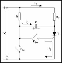 Since it is
a high-current and high-voltage switching element, experts have tried to develop different solutions for turning off the
thyristor. Several versions can be found on the Internet. The common feature of some of them is that a negative
voltage pulse is connected to the thyristor with a capacitor. According
to the schematic diagram shown here, after switching on, the voltage of the
charged capacitor is added to the terminal voltage Vi and momentarily
switches a negative voltage on the thyristor. This causes the thyristor to turn
off, then turn on again under the influence of the control voltage, and the
capacitor starts charging again. The principle seems simple, but the circuit
design requires a lot of time and attention.
Since it is
a high-current and high-voltage switching element, experts have tried to develop different solutions for turning off the
thyristor. Several versions can be found on the Internet. The common feature of some of them is that a negative
voltage pulse is connected to the thyristor with a capacitor. According
to the schematic diagram shown here, after switching on, the voltage of the
charged capacitor is added to the terminal voltage Vi and momentarily
switches a negative voltage on the thyristor. This causes the thyristor to turn
off, then turn on again under the influence of the control voltage, and the
capacitor starts charging again. The principle seems simple, but the circuit
design requires a lot of time and attention.
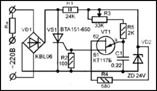 The other part of the switching
circuits also contains a thyristor, which switches a reverse voltage between
the anode and the cathode. This voltage creates a current in the opposite
direction to the anode current of the switched-on thyristor. This solution is
not simple either and increases the production cost. Forced commutation can
also be solved with a UJT transistor. The method of doing this is shown in the
attached figure. Experts in the semiconductor industry tried to overcome this
problem by developing a turn-off thyristor. This can also be turned off with a
control pulse via the Gate electrode.
However, the GTO (Gate-Turn-Off Thyristor)
did not achieve a breakthrough success. Its application is hindered by
the fact that 10% of the anode current is required for its switching on, while the turn-off current can reach 50% of the
anode current. These requirements require a complicated control
circuit. Therefore, it is only manufactured in high-voltage and high-current
versions, which are quite expensive. (They cost between $30 and $3,000. They
are also sold on AliExpress, but they are not cheap either.)
The other part of the switching
circuits also contains a thyristor, which switches a reverse voltage between
the anode and the cathode. This voltage creates a current in the opposite
direction to the anode current of the switched-on thyristor. This solution is
not simple either and increases the production cost. Forced commutation can
also be solved with a UJT transistor. The method of doing this is shown in the
attached figure. Experts in the semiconductor industry tried to overcome this
problem by developing a turn-off thyristor. This can also be turned off with a
control pulse via the Gate electrode.
However, the GTO (Gate-Turn-Off Thyristor)
did not achieve a breakthrough success. Its application is hindered by
the fact that 10% of the anode current is required for its switching on, while the turn-off current can reach 50% of the
anode current. These requirements require a complicated control
circuit. Therefore, it is only manufactured in high-voltage and high-current
versions, which are quite expensive. (They cost between $30 and $3,000. They
are also sold on AliExpress, but they are not cheap either.)
During my experiments, it occurred to me that this circuit does not excite itself, but receives the control signal from a signal generator. Therefore, it can also output a sine wave or a square wave with a negative half-period. Therefore, the thyristor could be turned off during the time axis. My hope did not come true. The negative voltage should not be connected to the control electrode, but to the thyristor. The current flowing through the thyristor should be made negative, in the opposite direction. The literature also states that the diac can be replaced with a triac. In this case, the diac connected in antiparallel will not be used.
This goes without saying, but it struck me that my generator actually produces a negative half-period. And not a little. The reverse self-induction voltage peak can reach six times the amplitude of the supply voltage. I was curious about what the triac has to say about how it behaves in this circuit. There is plenty of reverse current here. Despite this, the triac behaved like the diac. After switching on, it refused to turn off. Moreover, it got a little warm.
Now I only have one option left.
I took out the PA1 type 25 A amplifier from the Miboxer company. According to
its brochure, it is controlled by Pulse Width Modulation (PWM). However, the
manufacturer does not state at what frequency or frequency range the device
operates. It is not very encouraging that this circuit does not regulate the
output current with a thyristor, but with a
MOSFET. Despite this, the manufacturer says that it can switch a
maximum of 25 A. Well, we will see how much it can switch with an inductive load, with six times the self-induction
voltage. With such a load, the frequency of 10 Mbps (1.2 MHz) is also doubtful, although control with
optical coupling can work wonders in many cases. (The attached picture shows
the circuit diagram of an optocoupler 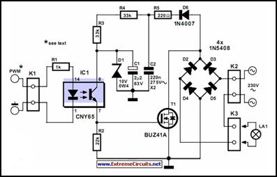 LED
dimmer.)
LED
dimmer.)
After a thorough study of the device, which is barely larger than a matchbox, it turned out that I won't get far with it. This is a PWM-controlled amplifier, which is not much different from phase-splitting power regulators. The difference is that here the circuit does not cut continuous slices from the signal shape, but rather the regulation is done with pulses. The amplitude of the pulse is always the same, only its width changes. Its width determines how long the MOSFET should be open or closed. The rather high power of 25 A compared to its heat sink can be attributed to the fact that the transistor is always completely off or completely on. Thus, it does its job almost without heating (dissipation). This feature is similar to to the thyristor, the only problem is that PWM control occurs at a given frequency.
This was confirmed by the response to my letter to the manufacturer: “The amplifier cannot change the signal frequency. The input frequency is the same as the output frequency. If you connect a product of another brand, then the output should be a PWM signal.” The letter also revealed that Miboxer produces a controller for its own amplifier, but it is nowhere to be found. In another letter, they stated that they had entrusted the distribution of their wide range of products not to the Chinese AliExpress, but to the American eBay online store.
After ordering their own controller, I measured the two connected units. According to the oscilloscope, this device operates at 650 kHz and changes the pulse width at this frequency. This made me very sad. I also ordered an amplifier that is assembled together with the controller, and the brightness control is done by a potentiometer is doing. Since this is made for colored LED strings, I thought it would work in a wider frequency band. Unfortunately, it doesn't. Its operating frequency was also 650 Hz. Therefore, you can't make a broadband, high-power amplifier from these circuits either.
This closed the circle. It seems that it is not possible to make a perfect high-performance current chopper with electronic components. Tesla had a much easier job. He did not need a diac, a triac, or even a MOSFET. He made a commutator that he drove with a DC electric motor. He collected the signal with a carbon brush mounted around the commutator. The frequency of the signal depended on the speed of the motor. When the carbon brush was on the copper slice of the commutator, the resistance of the current chopper was zero, and on the insulation between the two copper plates it was infinite. Thus, there was no dissipation, no saturation, no degradation of efficiency. The amplitude was the same at high frequencies as at low frequencies. Moreover, he received a much more efficient soliton signal, not a square wave. He only had one problem with this signal generator: if the carbon brush wore out, it had to be replaced.
Before I stopped this experiment, I tested whether the potentiometer version could handle the 30 A load. Instead of an LED string, I connected 2 24 V 100 W halogen lamps to it in parallel. According to the brochure, the amplifier's load capacity is 700 W at a 24 V supply voltage. This 200 W load did not cause any heating in it. I then adjusted the supply voltage to 12 V and connected my small spiral coil with an internal resistance of 2 Ω to it. The spiral coil heated up strongly, but the amplifier could handle the load. After that, I replaced the small spiral coil with the large spiral coil with a diameter of 15 mm. This did not heat up in the slightest. The amplitude of the self-induction voltage spikes was 80 V.
I then connected the 24 V supply voltage. The amplitude of the self-induction voltage spikes increased to 90 V. (When using large coils, the self-induction voltage already depends on the supply voltage.) I monitored the increase with an oscilloscope. As I wound the potentiometer up, the generator suddenly stopped. It became short-circuited, destroyed. The two MOSFET transistors could no longer handle this current. I disassembled the device. It contained 2 small, TO220-packaged MY1707 incremental MOSFET transistors. According to the catalog, their maximum voltage was 70 V and their maximum current was 80 A.
I did not despair because of the loss. I thought that I had much better transistors, 100 V and 350 A. I eliminated the two short-circuited transistors and replaced them with two large TO247-packaged MOSFETs. The result was very disappointing. The device worked, but the transistors were getting very hot. They were almost glowing at 1 A. I didn't know what to make of it. I looked up the datasheets for both transistors on the Internet. It turned out that the problem was with the minimum Gate voltage. When I measured them with an oscilloscope, the Gate voltage of the small transistors was 4 V, which was enough to fully open them. (The opening was so great that from the 10% potentiometer setting, the supply voltage appeared in full at the output of the device.) That's why they were able to switch the high current without a heat sink. (There is no heat sink. The two transistors were soldered to the printed circuit board, on a copper foil about 1 cm wide.)
My transistors, on the other hand, were also sweating on the heat sink. The problem was that these high-current MOSFETs open completely at a Gate voltage of 7 V. 4 volts was not enough for them. They couldn't get past the initial, curving phase of the output characteristic, so they only output half of the supply voltage. The rest remained in them, which they were forced to dissipate. However, the biggest disappointment was not caused by this, but by the control method. I expected much more from PWM control. Examining the oscilloscope output signal, it turned out that this device does nothing more than change the duty cycle (DUTY) from 0% to 100%. If other devices do this, then PWM is not a great invention. It is not much different from phase-splitting voltage regulation. It is also very similar to it because this device does not operate with square signals, but with a two-way rectified sine wave (Full-Wave). In this case, I don't understand why the Miboxer power amplifier cannot be controlled from a signal generator? The DUTY value can also be changed on the function generator.
I ordered this potentiometer dimmer because it was very cheap. It looked very similar to the Miboxer product. It could easily be a poor copy. Hoping that Miboxer could do much more, I wanted to order their control unit for it. While I was searching for the best deal in online stores, I came across a surprising discovery. I found a PWM generator that can be controlled in a wide range from 1 Hz to 150 kHz. It does not operate at a factory-set frequency, but its frequency can be increased in 1 Hz steps up to 150 kHz. Why they stopped there, I don't know.
I also wrote a letter to Miboxer asking if they could change the working frequency to other frequencies. If so, then there would be no problem with this broadband control. The answer was encouraging: “The input frequency is the same as the output frequency.” Now all that was needed was to find out what the cut-off frequency was. The Chinese have now replied to my letter. It said: “The PA1 frequency range is 1 MHz, within 1 MHz is no problem.” Great! Now all we need is a broadband PWB generator operating up to 1 MHz, and we can make a high-power signal generator, which would be greatly needed in almost every laboratory. Current signal generators can only output 250 mA with a max. amplitude of 20 V. This is 5 W of power, which is only enough for control. However, in this configuration, 600 W of power would also be available.
The need for signal generator control is not only due to the wide frequency band. The waveform of factory frequency generators does not maintain its regular square shape up to 80 kHz, but up to 1 MHz. Then this also starts to distort. Above 5 MHz, its shape is more like a sine wave. A regular square signal is very important because the PWM controller can only fully open the amplifier's MOS¬FET transistor if it produces maximum amplitude. If the square signal is distorted, the amplitude of the control voltage decreases. Because of this, the MOSFET does not open completely. It has to dissipate the remaining voltage in it, which starts to heat up. Therefore, it is not possible to make a PWM controller from any other waveform.
While the broadband PWM control unit was arriving, I looked into the Miboxer power amplifier. When I opened it, I couldn't help but be surprised that it didn't have a heat sink either. However, it had not 2, but 5 SMD MOSFET transistors connected in parallel. The AP80N03D transistors were also soldered to the printed circuit board. According to the catalog, the opening voltage of this MOSFET is 1.5 V, which guarantees the full opening of the power amplifier when all the control circuits are switched on. Its dissipation was further reduced by the fact that its peak voltage is only 30 V. However, its maximum current is also 80 A. It was impossible to map the circuit because it was mounted on a multilayer printed circuit board, which was sprayed with hard green varnish on both sides.
I couldn't help but be surprised at the price of the broadband PWM control circuit. They asked for only 463 forints ($1.50). This panel has 3 integrated circuits and 2 microprocessors. On the other side is a two-line LCD display. How can such a complicated device be manufactured for so much, with VAT and customs duties already included in the price? The Chinese probably want to undercut Western industry, so they sell their products far below production cost. If this device were manufactured by an American factory, it would cost at least 10 thousand forints. If their plan succeeds, Western industry will be completely dismantled.
After that, the Chinese will start increasing the prices of their manufactured goods to such an extent that the loss will be more than repaid. Our politicians do not perceive this danger and do nothing about it. Also, the American president has imposed a 145% tariff on Chinese goods, but it will not go far, because the Chinese have responded with an 85% import tariff on American goods. This tariff war will not bring a radical solution. Western companies would have to give up extra profits to stay afloat. However, they are not willing to do this. Western employees are not willing to work for less wages either. In fact, they are recently demanding the introduction of a four-day work week. This will end badly.[39]
The wideband PWM generator arrived 2 weeks earlier than promised due to airmail delivery. Before I connected it to the power amplifier, I studied its operation. Unfortunately, it cannot fully meet the parameters stated in the brochure. I didn't like the control method either. Based on the photo, I thought it had capacitive step switches. Instead, they put microswitches on it. That wouldn't be a problem, but the spring of the microswitches is so strong that by the time we reach 150 kHz by pressing in a 1-digit scale, our fingertips go numb. We can protect ourselves against this by pressing with a short, rectangular plastic rod. Fortunately, there is also the option of fast frequency switching. By pressing and holding the forward-backward button, the circuit automatically sweeps through the entire frequency range. This way, we stop where we want.
It is annoying that while stepping, dots indicating local values appear between each digit. The brochure describes what frequency value this corresponds to, but this is completely illogical. We are better off connecting our oscilloscope or the Ext.In input of our function generator to the PWM output. (By pressing the Measure button of the oscilloscope, the instrument displays the real frequency value with an accuracy of two decimal places. For the function generator, press the Meas button. From this function, we can return to normal signal generator mode by pressing the Wave button.) This check measurement is also important because, according to the brochure, the value shown on the display can differ by 2% from the real value. (In my case, the LCD display of the board version showed a value 3 kHz higher than what the oscilloscope and function generator showed.)
There is also a problem with the cut-off frequency. The amplitude does not decrease below the supply voltage up to 100 kHz. Above this, however, it gradually decreases with a 12 V supply voltage, and at 150 kHz only 4.2 V can be measured. The situation is better with a 24 V supply voltage. In this case, the amplitude decreases to only 10 V at 150 kHz. Setting the DUTY value is not tiring, but it is also inaccurate. The 50% duty cycle is only achieved in the range of a few Hz. As the frequency value increases, the pulse width gradually decreases. At 100 kHz, 80% must be set to maintain the 50% duty cycle. Moving upwards, the shape of the CMOS square wave signal in the positive range also becomes slightly distorted, but this is not too disturbing. (This is a common phenomenon with cheap square wave generators.)
Overall, this PWM square wave generator is not a bad device, it is well worth its price. If we keep it under control with an oscilloscope connected to its output, it can be used well for development purposes. A control measurement is also needed because this cheap generator is probably not able to correct value fluctuations resulting from aging or environmental temperature changes. There are cheap square wave generators equipped with a helical potentiometer that have similar accuracy, but they do not have a PWM output. And we need this to create a high-performance function generator.
So let's see if we have the opportunity to do this. I connected the mini PWM signal generator to the Miboxer PA1 type power amplifier. (I had previously opened its case to check the heating of the 5 MOSFETs. I did not want to mess with it like with the previous power amplifier.) This danger did not threaten us this time, because after proper connection, the amplifier did not start. When measured with an oscilloscope, the optocoupler heavily loaded the output of the PWM square wave generator. At a 12 V supply voltage, the amplitude decreased to 3.5 V.
At first I thought that this was not enough for the power amplifier, so I started to gradually increase the supply voltage. The amplifier started at 23 V, and at 24 V the two halogen bulbs burned at full brightness. However, I was not impressed by the success. After a few seconds, the MOSFETs began to heat up intensely. After 10 seconds, they got so hot that the power supply had to be turned off. However, only 3 A was flowing through the 5 transistors. I don't understand what's wrong. Why is a 25 A power amplifier glowing at 3 A? The same situation as with 350 A MOSFETs. They were already sweating at 2 A load. At first I thought that the problem here was that the input voltage was not high enough, so the transistors got stuck at the elbow of their output characteristic. However, in this case, the full supply voltage (24 V) appeared on the load, which shows that the transistors are fully open. So why can't they handle the 3 A load?
Finally, I increased the supply voltage even more. At 26 V, the two halogen lamps were already dazzlingly bright, and the transistors stopped heating up. It seems that I managed to completely bring the 5 MOSFETs out of the elbow of their characteristics. With a 50% duty cycle, the 5 transistors remained at room temperature throughout the entire frequency range. After that, I started to increase the DUTY value. At 80%, the transistors started to heat up a little. Therefore, DUTY should not be set to a value higher than 50%. It is no coincidence that manufacturers of function generators also set the duty cycle to 50%. I went back to 50% and increased the supply voltage further. The supply voltage of the square wave generator was allowed to be 30 V. The amplifier could handle this, and the transistors did not heat up either.
Since I ordered the packaged version of the PWM signal generator, I also connected it to the amplifier. It didn't start either. Otherwise, the packaged version is no different from the assembled printed circuit board (board) version. Its parameters are the same. However, pressing the buttons is more difficult, it is only possible with a fingernail. Interestingly, here the frequency value set on the LCD display exactly matched the value shown by the oscilloscope. At a supply voltage of 24 V, the DUTY value is also the same.
It was a big surprise that the packaged version showed a regular square wave at 150 kHz, with an amplitude of 12 V. Perhaps the manufacturer subjects its products to a preliminary selection. It puts the best in a plastic box and sells it at double the price. The rest are sold in a board version, at half the price. Therefore, we are better off ordering the packaged version. It also costs only $ 3. Unlike function generators, this small square wave generator retains the previous settings. When it is turned on again, it will set to the same frequency and DUTY value as before.
I am happy to announce that I managed to make a high-performance signal generator. The PWM signal generator costs $3, and the Miboxer power amplifier costs $3.5. For $6.5, I created a function generator with a load capacity of 20 A. I increased the load capacity of the signal generators by 80 times from 250 mA. And its output resistance is not 50 Ω, but 1 Ω. It is true that this signal generator only outputs a square wave, but most developments require this, and sometimes a sine wave. Almost no one uses the other waveforms (Triangle, Pos-Ladder, Neg-Ladder, Exp-Rise, Exp-Decay, Sinc, Lorenz).
This device only requires a 600 W stabilized power supply that can be regulated from 0 to 30 V. (A recommended type is in the compressed folder. The power supply manufactured for LED strings is not suitable for this because it cannot handle the inductive load.) The whole thing needs to be put into a common box. It needs to be equipped with network and BNC connectors, and the high-performance function generator can be put on the market. A significant advantage of the PWM amplifier is that it does not emit EMI. It does not interfere with analog radio.
There are also disadvantages to this generator. One is that its maximum frequency is only 150 kHz. However, this may increase to 1 MHz during later developments by the manufacturer. (This is how much the Miboxer amplifier can amplify. This problem could also be solved if the internal square wave generator were removed from the mini PWM signal generator. In its place, a BNC connector would be inserted, to which a laboratory function generator could be connected. This would be necessary because to kill microbes, frequencies of tenths or even hundredths of Hz are needed, but with the mini PWM signal generator, only whole Hz can be set.
Miboxer could also carry out this development. To do this, the PWM converting microprocessor of the mini PWM signal generator would have to be moved to their amplifier. I tried to persuade the Miboxer developers to do this, and they were very willing in this matter. First, they asked me what I needed this generator for. I wrote to them about the suppression of global warming, the need for a paradigm shift, and for this I would need high-performance frequency generators. I managed to arouse their interest. Then the I tried to convince the developers of the mini PWM signal generator to use an external function generator instead of the internal signal generator. Since I couldn't find the address of the Chinese manufacturer DollaTec anywhere, I sent the letter to our distributor. However, this letter remained unanswered.
On the other hand, I would like a high-performance power amplifier for the magnetic wave generator, which can be loaded with several amps. The question is, what does the Miboxer amplifier say about inductive loads? The manufacturer prohibits its use due to the counter-inductive spikes. The reverse voltage of the MOSFETs in the Miboxer is 30 V. The self-induction voltage peaks of the double spiral reach 80 V. This will probably cut off all 5 MOSFETs. Let's try it!
Before that, however, I wanted to find out why my amplifier made with a 350 A MOSFET was getting hot. I made only one change to the circuit. Instead of the double coil, I used two 100 W halogen lamps as a load. At a 12 V supply voltage, the amplifier behaved the same as with an inductive load. The IRFP4368 type MOSFET also got hot. Unlike the PWM amplifier, the transistor did not open completely here. It did not output the full supply voltage. It kept 1 V for itself. This voltage, multiplied by the load current, created such a high dissipation power that the MOSFET started to heat up again. I thought the transistor did not open completely because it did not receive enough control voltage. Therefore, I increased the amplitude of the function generator from 7 V to 20 V. The situation did not change.
I also looked at the frequency response of the amplifier. This did not change either. Above 250 kHz, the amplitude also began to decrease rapidly, which caused the MOSFET to heat up even more because it had to dissipate the trapped voltage. In addition, the square wave signal was distorted. There could be two reasons for this deplorable result. One is that the MOSFET type is not suitable. It should not have been the maximum current path, but the path with the lowest internal resistance and a low maximum voltage. Another possible reason for the failure is the inadequate control. It is possible that pulse modulation is more efficient at opening and closing the transistor than the waves of the function generator.
I quickly dispelled this uncertainty. I took the encapsulated PWM generator and connected it directly to the MOSFET Gate electrode. A miracle happened. The transistor opened completely here too, and the supply voltage appeared completely on the load. This stopped the heating. It seems that PWM control is a great invention after all. However, this ideal state did not last very long. Above 30 kHz, the voltage on the load started to decrease, causing the transistor to heat up a bit. The signal shape was also distorted. The Miboxer developers prevented this harmful phenomenon with compensating circuits.
So, let's see what happens here at a 27 V supply voltage. The lamps were blindingly bright, 2.6 A flowed through them, but the 1 MOSFET did not heat up either. Controlled by a function generator, an egg could have been fried on the heat sink containing 2 transistors after just 10 seconds. I checked the frequency response here too. Above 30 kHz, the signal shape also started to distort in this case. At 150 kHz, only 22 V of the 27 volt supply voltage reached the load. The MOSFET was forced to dissipate the remaining 5 V, which caused it to heat up a lot. For this reason, it is recommended to switch to a combo consisting of a mini PWM generator and a Miboxer amplifier.
The only question is what they say about inductive loads. The mini PWM generator will definitely not fail, because the optocoupler protects it from inductive voltage surges. I will be very sorry if the Miboxer amplifier breaks down. I cannot repair it, because SMD components cannot be replaced with a soldering iron. For easier reference, the combo of the mini PWM generator and the Miboxer amplifier will be called a PWM function generator from now on. In order to reduce the expected damage, I did not use the Miboxer, but one of the previously ordered 120 A MOSFETs as an amplifier. And of the two PWM signal generators, I connected the cheap board version to it.
My caution was not in vain, because during the experiments, two of my MOSFETs also broke down. The end result was that 3 A now passed through the mini spiral coil, which caused the 0.7 diameter copper wire to heat up in seconds. However, the transistor did not heat up at all. So I put a large double spiral wound from 1.5 mm diameter enameled copper wire on it. 6 A passed through it. This finally started to heat up, but it only became warm to the touch. The MOSFET didn't heat up this time either. Finally, I took out the Miboxer amplifier. I was afraid that the 70-80 V self-induction voltage peaks would cut off the 30 V reverse voltage MOSFETs. The transistors didn't have any problems. The 27 V supply voltage didn't destroy them either. I was amazed how this could be. When I measured the output with an oscilloscope, it turned out that the Miboxer had eliminated the 70-80 V self-induction voltage peaks. I measured regular square signals on the double spiral. I don't know how the developers did this. It's impossible to find out, because the printed circuit board is covered. They certainly didn't shunt the output with a diode, because that would have blown after a few seconds. This procedure did not reduce the electrical radiation of the double helix. It remained unchanged
Now all that was needed was to increase the 150 kHz frequency of the mini signal generator to 1 MHz. I managed to convince the Miboxer developers to do this. First, they asked me what I needed this high-performance signal generator for. I wrote to their manager that I was working on sub-electronics developments and wanted to reconstruct the inventions of Tesla, Raymond Rife, and German and Italian inventors. My goal was to stop global warming and save nature. Upon reading this, the Chinese did not consider me a quack, but made a fair offer. (In China, traditional healing goes back thousands of years. It is not considered quack. The Chinese and Japanese believe in the existence of extraterrestrial civilizations. In China, it is well known that the Yellow Emperor was an extraterrestrial. In India, however, the Vedas list the earthly activities of otherworldly gods on hundreds of pages.) In Asia, they approach these things quite differently. Scientists in these countries cannot fool the people. They believe in their “legends”.
Miboxer’s response was: “Thank you for sharing this information. You are a good engineer and you are doing the country a favor. We can customize 1 MHz for you. But the MOQ is 1000-2000 pcs.” Well, here is a limitless opportunity. I could provide the world’s developers with this high-performance function generator, which every laboratory desperately needs. But I can’t, because setting up a factory costs hundreds of millions, and I don’t have any money. That’s why I can’t manufacture the complete fire and burglary protection product line I developed. I have also developed cheap resistance, inductance and capacitance decade cabinets, but I can’t put these into production either. Yet they would cost a tenth of the price of the currently expensive decade cabinets. Beyond that, I have dozens of better ideas for what else could be produced, but I don't have the money for any of them.
Half of my pension is spent on buying small amounts of components. I try to incorporate these into my developments, but the financial constraints greatly hinder the efficiency of my work. AliExpress sends me daily product descriptions. I found a mini PWM amplifier in them. The Chinese try to minimize the use of materials. They only use as much raw material in each of their products as they really need. That is why they are masters of minimization. In their brochures, they put a three-fold enlarged image of their products. Then, when the goods arrive, you have to use a magnifying glass to find where they are in your palm. The 300 A MOS Trigger Switch Driver Module Transistor PWM Regulation Switch Control Board I ordered, for example, is 14 × 14.5 mm in size.
They squeezed the components so tightly that the PWM input no longer fit on it. One can only guess which capacitor or resistor of the amplifier the controller should be soldered to. (For soldering, use a max. 60 W soldering iron so that the SMD components are not damaged.) Counting the legs of the tiny amplifier, the 300 A version has 7 MOSFETs. The optocoupler was also shoved into this small case, which only has a current rating of 280 A. This is certainly peak current. The effective current endured for a long time is usually one tenth of the peak current. But considering its size, even 28 A seems incredible. (The brochure indicated 100 A as a continuous current.) Let's see what this miniature amplifier is actually capable of.
I came across a new type of mini PWM controller in the AliExpress notifications. The frequency range of the ZK-PP2K PWM Driver is the same as the previous, already tested version. It differs from it in that it can also be used in Pulse mode. Pulse mode is used in digital technology. It is mostly used as a clock signal. It synchronizes measurements and ensures accurate data collection. Such a pulse generator is also found in cardiac pacemakers. It is useless for them because it produces small spikes as pulses. These narrow pulses are not able to effectively cause changes in the body. (For medical purposes, a 50% duty cycle is suitable.) Engineers like it because narrow pulses are easy to produce. Therefore, it is not uncommon to find pulse generators that operate up to 200 MHz. However, for medical purposes, a cut-off frequency of 1 MHz is sufficient.
However, this device has a special feature. An amplifier is installed. It has a TO220 incremental MOSFET, which is said to have a load capacity of 8 A. In addition, the brochure stated that it is also suitable for speed control of low-voltage DC electric motors. In other words, it can handle inductive loads. Let's see what is true of this. After its arrival, it turned out that its square wave generator is no different from the previous basic version. Its frequency range also extends from 1 Hz to 150 kHz. This also only provides regular square wave signals up to 80 kHz. Above this, the signal becomes convex, then becomes a sawtooth signal. The special feature of the device is the Pulse mode. To try it out, hold down the SET button for 6 seconds. In this mode, you can adjust the width of the pulse and pause signal as desired. The set time range extends from 0.000 s ~ 9999 s. (This is almost 3 hours.) The P+ and P– buttons can be used to set the positive pulse width time, and the N+ and N– buttons to set the negative pulse width time. This function works perfectly. We can make an excellent monostable multivibrator out of it, but we don't need it for that. So let's exit it. (Hold down the SET button.) The ON button can be used to enable or disable the output signal. (In the previous basic version, a separate switch is required for this.)
Let's see what the amplifier can do. The positive feature of the device is its wide supply voltage range (DC 3.3V–30V). It opens completely at 4V and does not heat up. (The Miboxer amplifier with this PWM controller opens completely at only 26V supply voltage.) I connected 2 100W halogen bulbs to it as a load, in parallel. I started increasing the supply voltage. Nothing happened up to 12 V. The device did not heat up at all. By further increasing the supply voltage to 24 V, the 80 A MOSFET became short-circuited. However, only 3 A flowed through it. This device is only suitable for speed control of mini DC motors. For brightness control, a maximum of 200 W LED lamp or LED string can be used. You cannot make a high-performance function generator from this.
Since the delivery of the 300 W and 280 W mini amplifiers was delayed, I measured the load capacity of the Miboxer PA1 amplifier. I had no idea that I was inexplicably facing a serious loss. Unsuspectingly, I turned on the combo consisting of the encapsulated PWM controller and the PA1 amplifier and connected the oscilloscope to the output. The whole system started to go haywire. The power supply, the amplifier, the PWM controller and the oscilloscope all went haywire. After half a minute, the controller gave up and shorted out. So I took out the unencapsulated (board) version of the PWM controller. As soon as I turned it on, the integrated circuits started to sweat, and then the entire panel burned down, smoking. I checked the connecting cables to make sure I had connected them correctly. I found no errors. Since the amplifier opened at 26 V, I thought it had failed due to overvoltage. I looked at its brochure. It said that its supply voltage range was 3.3–30V. So what was the problem?
After that, I had no choice but to take out the broken ZK-PP2K PWM Driver. It worked, but the power amplifier transistor was broken. I cut off its legs and soldered one of the 120 A MOSFETs in its place. I was worried that this high-current transistor would not open completely here either, and would get hot because of it. That was not the case. When I measured it, it turned out that it was fully open here. Its output voltage was the same as the supply voltage. It turned out that full opening does not depend on the type of MOSFET. The control circuit opens it completely. How it does this cannot be found out, because the foil connecting the components is hidden. The manufacturer used a multilayer printed circuit board, and the copper foil is inside. There are only through-hole solder points on the top and bottom of the panel. So the circuit cannot be mapped. I was also surprised that the amplifier now opens at 18 V instead of the previous 26 V supply voltage. Another positive aspect of this control circuit is that it somehow eliminates the self-induction spikes of the double spiral.
It seems that the previous damage was necessary to reveal these positives. However, the PA1 amplifier's load capacity was disappointing here too. The manufacturer specified a max. 25 A load capacity. However, during the measurement, it turned out that the 5 mini MOSFETs in the amplifier start to heat up at a load of 8 A. Since it has no heat sink or fan, it will overheat and short-circuit during prolonged use. I wonder how much the 300 A mini amplifier can handle. I would be happy if it could withstand even one tenth of this value. If not, then there is only one solution. The ZK-PP2K PWM Driver must be used alone. Let's take it apart and solder a thin, tinned, stranded, insulated copper cable to the 80 A MOSFET Gate leg, and lead it out of the housing next to the terminal blocks. Then you need to order the 100 mm long heat sink recommended in the compressed appendix, and install 10 parallel-connected STP80NF03 type MOSFETs on it. (This transistor is also in the PA1 amplifier, but in SMD version.) This way, its load capacity will definitely reach, or even exceed, 20 A, and you won't need a fan.
The heat sink is mounted on a double-sided printed circuit board. The circuit paths must be tinned after etching. At the bottom of the printed circuit board, there should be a foil about 2 cm wide connecting the Source legs of the MOSFETs. On top, there should also be a foil that is also 2 cm wide. The heat sink must be screwed onto this, and the Drain legs of the MOSFETs must be soldered to it. First, we grease the back of the MOSFETs with heat sink grease and place them in the holes. Before soldering the legs, screw them to the heat sink, but only loosely so that they do not touch. Solder the legs, then screw the transistors firmly to the heat sink. Lead the Gate legs out of the Source foil on the other side of the board and connect them in parallel. To do this, solder the thin control cable from the PWM Driver.
Solder the power supply ground point (U–) to the Source rail. To do this, use a min. 1.5 mm thick stranded, tinned, insulated cable. Solder the same thick cable to the Drain rail. This will be the load minus terminal (OUT–). The plus terminal (OUT+) must be led from the power supply U+ terminal. By connecting the Source and Drain legs of the MOSFETs directly to the power supply terminals with a min. 1.5 mm diameter, tinned, stranded, insulated copper cable, we disconnect the PWM Driver from the power amplifier.
Do not use a 350A MOSFET because the control circuit cannot fully open it. I tried. After it could not open completely, it got hot in a moment. Not only the MOSFET was destroyed, but also the driver control circuit. This was manifested in the fact that after replacing the MOSFET power amplifier with a 120 A one, the regular square wave signal was distorted. Because of this, the transistors of the PA1 amplifier also heated up a lot. This amplifier almost shorted out. The output terminals of the ZK-PP2K PWM Driver should not be used anymore, because if we draw the high current of the load from there, it will overheat and be destroyed. By the way, we can connect not only low-current loads to the output OUT+– terminals. We can connect them to the input of any PWM amplifier. Also to PA1. Just because there is a MOSFET transistor at its output, the ZK-PP2K PWM Driver does not lose its control circuit character. (The polarity of the load is especially important when using LED strings.)
The high-current Use a 200 W soldering iron to solder components. (A smaller soldering iron will overheat the MOSFETs when soldering the drain pins, causing them to fail.) To avoid overheating, solder the transistors with long legs. (Push them up on the heat sink so that it extends 2 mm beyond the other side of the printed circuit board. Create a cooling grille on the housing behind the heat sink so that the hot air can escape. The housing should be made of soft iron sheet to shield EMF radiation. In the case of EMI radiation, the housing can be connected to the ground point (U–) of the power supply. However, this is dangerous because if it touches the positive voltage of the circuit during development, it will cause a short circuit. If this grounding is unavoidable, the high-current function generator should be enclosed in an external plastic case.
After the ZK-PP2K PWM Driver failed, I ordered another one. It arrived relatively quickly, but it didn't last long. It worked the same as the previous one, but this time I didn't overload it. Nevertheless, it quickly failed. I thought I'd try disabling the output signal. I pressed the ON button. The control stopped immediately. It should have started again when pressed again. It did start, but there was no thanks in it. The power amplifier transistor became short-circuited here too. The reason for this is a peculiar phenomenon, the existence of which few people know. I used the two 100 W halogen lamps as the load. However, the tungsten filament incandescent lamp has an unpleasant property. At the moment of switching on, the cold filament draws ten times as much current as its effective current when it is glowing. The transistor could not withstand this magnitude of current surge. In normal operation, this is not a problem, because one of the integrated circuits of the controller outputs the opening signal with a delay. The control signal reaches its maximum after a few tenths of a second. However, the ON button pushes out the full amplitude in an instant. Therefore, if you use it to control the brightness of tungsten filament lamps, do not use this button.
The control device that has been destroyed in this way does not need to be discarded. The destroyed MOSFET can be replaced with the type recommended above. This is also not necessary if the solder point of the pinched Gate leg is led out of the device housing with a thin cable. This smaller current is also able to open the amplifier. When controlling the PA1 amplifier, screw the INPUTSIGNAL PWM terminal block to the (V–) input. And connect the (V+) input to the Power V+ connector, i.e. to the positive pole of the power supply. It's a bit strange that in n-type transistors the control current flows between the Gate and the ground (U–). Here, however, the role of the ground is played by the positive power line (U+).
After two months of waiting, the mini amplifier finally arrived. (If it had been connected to the back of a snail, it would have arrived here sooner.) First, a mistakenly ordered 40 A version arrived. When I picked it up, I couldn't believe my eyes. They sent me a 7 × 8 mm printed circuit board. All the components were mounted on it. I tried to find where the PWM input was on it with a magnifying glass. I couldn't find it anywhere. I wrote a letter to the webshop asking where to connect the PWM controller. They forgot to indicate this on the wiring diagram in the brochures. They didn't get a reply either. They leave it up to the customers to figure it out. I did the same thing, for lack of a better word.
The ends of a 1 kΩ and a 10 kΩ chip resistor were facing one side of the board, so I thought I would solder them to them. I took out my thinnest tipped soldering iron and two thin connecting wires. I didn't know what I was doing yet. The two chip resistors were about 0.5 mm apart, and the circuit's power input was right next to them. Therefore, there was a risk that the tin would flow into each other at the soldering points. To avoid this, I had to adjust the connecting wire left and right. The prolonged heating caused the copper foil under them to separate. The other resistor burned and detached from the board. This product is a scam. The Chinese are famous for saving raw materials, but in this case they went too far. Let's save what we can, I connected the power supply to the high-current wires to see how much short-circuit current this chip can withstand. It got hot at 2 A and shorted out.
I didn't even try soldering the 14 × 14.5 mm 300 A amplifier. I connected two pointed test leads to the chip resistors. After several attempts, I managed to determine the location and polarity of the PWM inputs. I also drew this in the factory brochure, with a green line. Its measurements were more encouraging. With a 12 V supply voltage, it didn't heat up until a 5 A load. It started to get hot at 6 A and shorted out at 8 A. Well, that's how much the 300 A amplifier could withstand. This is what transistor manufacturers do too. They also write a maximum current that is 60 times higher than it can actually withstand.
Since these mini amplifiers are useless, I looked around the AliExpress online store to see if there was an amplifier with an input. Fortunately, there was one. The same integrated circuit was used as in the 300 W mini amplifier, but they only dared to write 100 A as the maximum current. It also had 7 MOSFET transistors connected in parallel. The difference was that the manufacturer of this one mounted the integrated circuit on a 19 × 24 mm printed circuit board, so there was plenty of space for the inputs with independent soldering points. They also thought about fixing the panel. The connection of the high-current power lines was designed at the four corners of the panel, with large holes. If you put 2 mm diameter tubular rivets in these with spacers about 5 mm high, you can fix it stably to the base plate of the device.[40]
I ordered 5 of them right away. It wasn't a big expense, because they were selling for $1 each. I didn't order so many of them because I was going to ruin them, but I had an idea. I'll try to connect them in series. Since these samples didn't get hot up to 5 A, if 5 panels were connected in series, the load current would be distributed over 5 × 7, or 35 MOSFETs. This way I get an amplifier with a load capacity of 25 A. This way, I won't need a heat sink version. Miboxer's PA1 amplifier can handle 10 A without getting hot. 10 MOSFETs mounted on a heat sink will probably provide 20 A, but the aluminum heat sink is not cheap and takes a lot of time to install. The question is whether the ZK-PP2K PWM controller can open 35 transistors. Since, unlike bipolar transistors, the control current requirement of field-controlled transistors is almost zero, this is probably not a problem. This is also because there is a MOSFET power amplifier at the end of this PWM controller, which multiplies its power. (As already mentioned, this version integrated with the amplifier can still be used as a PWM controller. However, make sure to operate it with a 24 V supply voltage when connected to the PA1 amplifier. It is excited at 18 V and only opens fully above 20 V.)
Due to the high currents, be especially careful of the risk of short circuits. The Hongpoe 0 to 30 V adjustable, 20 A stabilized power supply included in the compact appendix can do more than what is written on it. Its voltage can be adjusted up to 48 V, and its maximum load capacity reaches 42 A. Therefore, do not leave any connecting wire bare, because if it touches any component, the 42 A short-circuit current will burn out all the transistors and integrated circuits. This will not destroy the power supply, because it is equipped with overload protection. This will only make it warm, but its fan will turn on.
To protect our circuit, set the power supply's overcurrent control helical potentiometer to the maximum current we require, currently 20 A. Turn it down to minimum current, then connect a heavy-duty 1 Ω resistor to the + and – terminals. A large double helix is best suited for this. If you haven't made one, look around in your laboratory and solder thick winding wires together until your resistance reaches 1 Ω. Use the helical potentiometer to set the supply voltage to 24 V, then connect the winding wire to its output. We turn the current control helical potentiometer up to 20 A. After that, in the event of a short circuit, the short-circuit current will not exceed 20 A. Above the set value, the voltage output by the power supply gradually decreases, which protects the circuit under development.
The over-regulation of the power supply makes it easier to choose the ideal power supply. It is easy to find that a 30 V supply voltage is not enough. At this point, we can go up to 48 V and see what voltage we need. If 20 A is not enough, we can also see what load capacity we need up to 42 A. If much higher, then choose a 1000 W or 1500 W power supply. For high-current developments, forget about the plug-in modeling panel. These modules are used by amateurs to develop melody bells. We need a robust, tubular rivet development board, which is not sold ready-made. The method of making it can be found in the compact appendix. To solder the tubular rivets, you need a 100 W soldering iron with a non-tipper soldering iron holder. The method of making it can also be found in the compact appendix.
Be sure to buy a zinc-coated soldering iron tip for the soldering iron. A nickel-plated soldering iron tip can only be used for a short time. Once a patina forms on it, tin no longer sticks to it. A copper soldering iron tip is not perfect either, because the oxide layer that forms on it can only be removed with sandpaper. A zinc soldering iron tip does not oxidize, and the scale that has burned on it can be wiped off in an instant with a wet sponge. After that, we can use it as clean as metal. A wet sponge cannot be used with a copper soldering iron tip, because it wipes off the tin layer applied after grinding. Scrape off the scale with a blunt knife. Using gray cleaning powder is also a good solution, but this also leaves behind dirt that can be removed with a knife.
We will also need connecting cables. Choose silicone insulated ones for these. They are more expensive than PVC insulated ones, but they are more flexible. Therefore, they do not sweep the table when moving the development board. In addition, silicone cables have extremely thin tinned copper wires inside, which greatly facilitates soldering them. Order AWG 14 cable in black and red. Its load capacity is 20 A. The cheapest one can be obtained from the TEMU store. Order at least 10 meters of each and cut them into 1 meter wide pieces. Make a version with clamps on both ends and a clamp on one end and a bare end on the other. Repeat this with banana plugs and tubular cable lugs. We will need all 6 versions. It is important that the cable with the tinned end is not only secured in the plugs with a screw or crimping pliers. Then solder the cable end with tin. This way, it will not loosen or anodize even after frequent use. (Before soldering, do not forget to put the plastic housing of the banana plug and the insulating tube of the clamp and the lug on the cable.)
Don't spare money for quality cables, because using them will save you a lot of trouble. If you need a shorter cable, wind one end into a spiral with a diameter of 2-3 cm so that there is no untidy cable forest on your desk. Get a strong pair of tweezers, because the thick cable gets hot during soldering, and you can't hold it with your fingers until the tin cools down. You will also need professional stripping pliers, because cleaning the cable end with a knife or side-cutting pliers is very difficult. (A recommended type can be found in the compact appendix.) Create conditions in your laboratory that allow you to work without obstacles and with precision. Don't waste your time sharpening the tip of your soldering iron or navigating through tangles of cables. Subotronics is a dangerous profession. Don't expose yourself to dangerous doses of magnetic radiation from side activities. Only bend over the circuit for as long as necessary.
The 5 pieces 100 A mini amplifier arrived relatively quickly. When I measured it, it turned out that it was the same as the 300 A mini amplifier, but they left room here to solder the connection wires. (If the controller and the amplifier are powered by the same power supply, the OUT+ output of the PWM controller does not need to be soldered.) So, let's connect them in parallel. This tedious and time-consuming operation was a big disappointment. First, I made a heat sink out of thick aluminum sheet to reduce any possible heating. This is where the problems started. Since I couldn't access the presumably metallic bottom of the integrated circuit soldered to the printed circuit board, I coated the top of the vinyl with epoxy metal glue and glued it to the heat sink. Then came the paralleling of the 5 terminals of the amplifier. Since I didn't have any silicone-insulated cable, this was also a nerve-wracking operation. The PVC insulation melted from the thick cables, and a veritable forest of cables formed on the small panels.
First, I tried the first amplifier. Despite the wiring on the back, it was functional. It only started to heat up at a load current of 4 A. After that, I turned on the second panel. I expected the load current to be divided between the 2 × 7, i.e. 14 transistors. This did not happen. Now both panels heated up above 4 A. I connected all five amplifiers to this. The result was catastrophic. Now all the panels heated up strongly. They heated up in seconds from a load current of just 2.5 A. The main reason for this was that the signal shape was distorted during parallelization. The 1 kHz square wave signal turned into a sawtooth signal, and the PWM controller could not open the 35 MOSFETs. Instead of distributing the load current through them, they shunted each other. The voltage remaining in them was dissipated. The heat sink did not help at all. The vinyl housing of the integrated circuits and the adhesive could not transfer the heat. This was a bad idea. So there was nothing left but to parallelize the MOSFETs mounted on the heat sink.
Fortunately, I didn't have to wait long for the 10 STP80NF03 MOSFETs, the heat sink, and the heat sink grease. The paralleling of the 10 transistors wasn't easy either. Drilling and tapping the heat sink, and connecting the transistor legs in parallel also required a lot of patience. The result was somewhat better, but it wasn't a triumph either. First, I connected it to the ZK-PP2K PWM controller. Since the power amplifier transistor was broken, I led out the hot spot of the Gate leg and connected it to the parallel-connected Gate electrodes of the 10 MOSFETs. I connected their Drain and Source legs directly to the power supply. This setup worked, but the self-induction voltage peaks of the small double spiral used as a load appeared. It turned out that the developers eliminate these voltage peaks on the power amplifier transistor, but how, it cannot be found out. There is an integrated circuit and some transistors around the MOSFET of the power amplifier, but they are not marked. The circuit they form cannot be mapped either, because they are inside a multilayer printed circuit board.
Well, that won't be good. After I ordered 12 pieces of the MOSFETs mounted on the heatsink as a precaution, I installed one of them in the ZK-PP2K PWM controller. That fixed it. Now there was no problem using it as a full-fledged controller via its terminals. However, the result was devastating. Since the power transistor of this controller was already heating up at 2.5 A, I expected that this would only happen at 25 A with 10 transistors mounted on the heatsink. Nevertheless, the 10 transistors were already heating up at a load of 5-6 A. Well, that's not enough. Much more is needed.
Since the Miboxer amplifier alone could handle 8-10 A of load without heating up, I decided to “shoe” it with the 10 external transistors. The easiest way to do this would have been to use PA1 as a driver and connect it to the heat sink transistors. However, using a 25 A amplifier as a driver is a luxury, even if you could get double that from the 10 heat sink transistors. So what I did was to take the Gate leg of one of the 5 internal parallel transistors and connect it to the Gate legs of the 10 heat sink transistors. The result was terrible. The 10 transistors shunted the internal 5 transistors. The signal shape was distorted and all 15 transistors started to heat up. The PA1 preamplifier was unable to supply 15 transistors with control current. Only the Miboxer developers could solve the expansion.
So I contacted their manager again. He mentioned to him that they had a 4-channel amplifier. What if I connected the 4 channels in parallel? Then it would be a 100 A amplifier? If that doesn't work, could they make an amplifier that would have 10 transistors instead of 5. This would make it 40 A when loaded with an LED string, and 16 A when loaded with an inductive load. The answer came the next day, and it wasn't encouraging. The lab manager said that there was nothing wrong with connecting the outputs in parallel on their four-channel amplifier (PA4), but that wouldn't increase its load capacity. In fact, it won't even be as much as the single-channel PA1, which is 25 A.
I also learned from him that: "In the case of an inductive load, the amplifier needs at least three times the load current. If the inductive load current is 20 A, then the amplifier must be able to output at least 60 A. Inductive loads are not really suitable for this type of amplifier." This is indeed the case. With my double coil load, the PA1 started to heat up at 8 A. There was only one option left. I asked him if I could connect 10 TO247 MOSFETs connected in parallel. The answer came very quickly, saying: “This solution is not feasible. The control voltage of PA1 cannot drive high-voltage, high-current field-effect transistors. For these, the voltage should be 10 V, but PA1 only has 4.7 V.
Finally, another interesting letter arrived: “MOSFET transistors need to be turned on and off quickly, not by increasing the frequency. The 1 MHz frequency causes increased heating of the transistors, as the number of cycles of on and off states increases. To speed up the conduction and switching processes, it is necessary to add dedicated MOSFET drivers.” In other words, it is necessary to order the development of a controller that can be used from 1 Hz to 1 MHz. To do this, 1000 or 2000 pieces would have to be ordered from them. But from what?
Since I have no money and cannot hope for support in this world that cares nothing about its environment, a bridging solution would be needed. In the midst of my thinking, I found a couple of IRFP4668 MOSFETs among my transistors. I looked at their datasheet, which revealed that they were 200 V Drain-Source and 130 A transistors. Since the 350 A MOSFETs previously did not open completely, I thought that these would do the same and would heat up at a load of 2 A. I inserted one into the simple power amplifier circuit I had previously used, which I controlled with a signal generator. To my greatest surprise, this transistor opened completely. At a Gate voltage of 9 V, the full It output a supply voltage, and at the pause signal the signal dropped to zero voltage. This way this MOSFET did not heat up under multiple A loads. However, the self-induction voltage peaks appeared here too.
It turned out that the excitation of the circuit due to long measuring and connecting cables, and the self-induction voltage peaks, can be eliminated not only by a diode connected in antiparallel to the load, but also by connecting a capacitor of a few nF between the Gate leg and the GND point of the supply voltage. The only problem is that the capacitance of this capacitor is different for each frequency value. However, the infinitely great advantage of this solution is that with the function generator, not only whole, but also tenths and even hundredths of Hz frequencies can be set, which is essential for healing and the destruction of microbes at the resonance frequency. Moreover, this frequency value does not change even in the event of aging and does not depend on changes in ambient temperature. In addition, there is no signal distortion. Even the cheapest function generator can output a regular square wave signal up to 1 MHz, while the square wave generator of the ZK-PP2K PWM controller can only do this up to 60 kHz. Above this, the square wave signal is strongly distorted, which prevents the PWM controller from operating properly, and this causes the output transistors to heat up.
So which way should I go next? In cooperation with the Miboxer company, there should be a medium-power function generator free of self-induction voltage peaks, or there should be a high-power and high-precision generator with self-induction voltage peaks. This dilemma could only be resolved by manufacturing and distributing both versions. The feedback from the testers would reveal whether these voltage pulses, which reach six times the supply voltage, have a beneficial or harmful effect on the body. However, the production and the salaries of dozens of employees would cost hundreds of millions of forints, and I only have enough money left to order the IRFP4668 MOSFETs and the large heat sink needed to mount them.
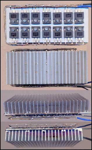 I was very surprised
that the 15 MOSFETs and the 150 mm long heat sink arrived after a week. My joy
was somewhat dampened by the fact that the planned 10 transistors did not fit
on it. Before ordering this heat sink, I measured the width of a TO247 transistor. The caliper showed 15 mm. Well, then 10 pieces will fit on it, I thought.
However, the width of the IRFP4668
MOSFETs was 15.5 mm, so the last one
was hanging halfway off it. Therefore, a 300 mm long heat sink must be ordered
for the high-power function generator. This will have three advantages. The
first is that the transistors do not have to be placed closely together. This
way they don't heat each other up. The second is that there is no need to drill
a thread into the fins. Due to the airy arrangement, the M3 screws that secure
the transistors can be drilled between two fins. The third is that 14 MOSFETs
can fit on this long heat sink. This
will increase the load capacity of the high-performance
function generator even more.
I was very surprised
that the 15 MOSFETs and the 150 mm long heat sink arrived after a week. My joy
was somewhat dampened by the fact that the planned 10 transistors did not fit
on it. Before ordering this heat sink, I measured the width of a TO247 transistor. The caliper showed 15 mm. Well, then 10 pieces will fit on it, I thought.
However, the width of the IRFP4668
MOSFETs was 15.5 mm, so the last one
was hanging halfway off it. Therefore, a 300 mm long heat sink must be ordered
for the high-power function generator. This will have three advantages. The
first is that the transistors do not have to be placed closely together. This
way they don't heat each other up. The second is that there is no need to drill
a thread into the fins. Due to the airy arrangement, the M3 screws that secure
the transistors can be drilled between two fins. The third is that 14 MOSFETs
can fit on this long heat sink. This
will increase the load capacity of the high-performance
function generator even more.
After ordering a smaller heat sink, I mounted the 14 transistors on it in two rows. (This is also good for testing.) The result was encouraging. I connected the large spiral coil to it as a load and controlled it with a CMOS wave from a signal generator. I set the control voltage amplitude to 10 V. At a 12 V supply voltage, 5 A flowed through the transistors, which did not cause any heating. I increased the supply voltage to 24 V. At this point, 12 A flowed through the transistors, which caused them to heat up a little. In the case of an inductive load, this is a very good value. This means that the maximum current for an ohmic load can reach 25 A. However, the excitation has not stopped. If the control unit to be developed by Miboxer includes a circuit that cuts off self-induction voltage peaks, the inductive load capacity can go up to 15 A. It does not depend on the MOSFETs, because they can still handle 16 A, although they have already become very hot here. Unfortunately, due to the lack of the Miboxer controller, I cannot complete this development. However, I would also need a high-performance square wave generator for my further work.
Due to the lack of support, I am forced to suspend this development as well. I can only give advice based on my experience so far. One of these is that in the case of inductive loads, the 30 VDSS MOSFETs used by manufacturers are not worth using. The lower the Drain-Source limit voltage, the easier it is to fully open and close the MOSFET. However, low-voltage transistors are very sensitive to voltage peaks, and due to their low maximum current, to overload. That is why my STP80NF03 type MOSFETs failed one after another. However, the IRFP4668 type MOSFET withstood the flogging well, although a couple of them also failed.
If 10 transistors mounted on the heat sink are exposed to overvoltage or overheating, it is not certain that all of them are broken. In this case, they must be unsoldered and their functionality measured one by one. The transistor tester of multimeters is not suitable for this, because they can only be used to measure bipolar transistors. FETs do not open at a Gate voltage of 0.6 V. To check them, set the multimeter to resistance measurement. Then measure the resistance of each layer. In a good MOSFET, all three legs should show a break in all directions. If the resistance between any two legs decreases, those two layers are shorted. If the resistance decreases only slightly, the transistor is still working, but it will heat up due to the leakage current. Therefore, do not use this copy any more.
As for good advice, it is also worth studying the Word files in the compressed folder. They contain offers of instruments and components necessary for development. These tips make our work much easier. It is especially advisable to read the advice on soldering, because a bad soldering can cause us a big headache. Unfortunately, reading is not fashionable these days. People have given up reading because they have to think while doing it, which is tiring. However, sub-electronics requires professionals who think intensively and read the literature every day. This also means that they have to be busy after working hours. Therefore, this profession was not invented for those who want a bourgeois lifestyle. Tesla was also forced to give up the pleasures of private life, which allowed him to achieve world-class results.
The field strength of the magnetic wave generator can be significantly increased with the combos described above. This allows the diameter of the double helix to be increased. Instead of Ø 0.7 mm, use Ø 1 mm enameled copper wire. The inner coil is wound on a Ø 3 mm metal tube and the outer one on a Ø 6 mm metal tube. The length of the coils is reduced to fit in a Ø 12 cm ceramic bowl. This can still be held in your hand. As the coil length decreases, their internal resistance also decreases, but the resulting increase in current can be tolerated by 10 parallel-connected MOSFETs mounted on an external heat sink. When using the generator, make sure to always set the exact frequency value before starting the treatment. Do not spin the frequency generator up or down during the treatment, as there are frequencies that have a harmful effect on the body.
Since this generator has not been extensively tested and I have not received any feedback, I am not convinced that this generator emits magnetic waves. According to the literature, in the case of bifilar winding or counter-directional magnetic excitation, the electromagnetic radiation loses its magnetic component and becomes an electric wave. Therefore, it is incorrect to call a coil formed from a double helix a magnetic wave generator. The term that most closely approximates reality is the Electric Wave Generator. Therefore, we will call it that way from now on. The name magnetic wave generator should be reserved for a generator that emits longitudinal waves to be developed later.
However, it is a big question how well this generator emitting electrical radiation will work in practice. The medical use of electrical current is not uncommon in combating various diseases. The Super Ravo Zapper, created by Czech and Slovak engineers, passes electrical current at different frequencies through the body in order to heal us. It is also suitable for the targeted destruction of microbes (viruses, bacteria, fungi). To do this, the resonance frequency of the microbe must first be determined under an electron microscope. The working principle of the device and the various case studies can be found in the description of the development entitled Cancer medicine. (Let's not be satisfied with opening the HTM version now. Let's download the compressed folder, because without the attachments we will not get a comprehensive picture of this treatment.) Many people do not believe in frequency healing. However, their doubts only last until they try them. This is what happened to the man who said this about his healing with the Zapper:
I had an open leg fracture as a result of a motorcycle accident. The fracture became infected, and a flesh-eating bacteria attacked it. It was horrible to see my leg rotting away. The infection didn't respond to antibiotics. My partner begged me to treat it with a Revo Zapper. He had one of these things, which I was very happy about when he grabbed the tubes, saying it would heal. Since they were already talking about amputation, I had nothing to lose. And it did!!! The infection stopped or something, stagnated for a while, and then started to heal. I didn't get antibiotics then, only this Zapper worked. My leg remained, but it did such terrible damage to the muscles that it was partially paralyzed. It looks very ugly, the muscle is missing in pieces the size of bread rolls. But this is my leg, not a prosthesis (artificial leg).
However, serious diseases, such as cancer, are difficult to cure with a Zapper. This requires intense magnetic irradiation. For this purpose, Czech and Slovak engineers developed the RPZ 14 and Athon 7 generators. The Cancer Medicine description also covers their operation. Both devices contain a plasma tube filled with noble gas. Their developers claim that they managed to obtain the documentation of Raymond Rife's plasma tube and copied it exactly. More precisely, it is not them, but a Canadian manufacturer whose name and address are being withheld. This plasma tube can be ordered separately from the Czechs, but it costs tens of thousands of forints. All we have learned about it is that it is filled with helium and also contains small amounts of other noble gases. The devices are not cheap either. Currently, the RPZ 14 generator costs 2.7 million forints, and the Athon 7 generator costs more than 10 million forints. The price of the Super Ravo Zapper has also increased to 277 thousand forints.
Laser generators treat using a different method than plasma generators. Unlike normal light, they do not emit photons that scatter everywhere, but a coherent light beam that propagates in a straight line. This creates a more intense healing effect in the body than color therapy. Its treatment areas can be read in the Medical Aids subfolder of the compressed folder. The strength of the laser beam varies. It is not cheap either. The price of the most powerful SL 1800 soft laser is 640 thousand forints. It penetrates 10 cm deep into internal organs, but serious diseases cannot be cured with it. Safe Laser is mainly used for pain relief, treating joint problems and curing skin diseases.
The experiment aimed at achieving the desired longitudinal magnetic radiation is the Primer Cube. According to its inventor, David LaPoint, this small cube-shaped device generates pulses of electrons and photons with a rotating magnetic field. However, this is not the case. This box contains strong neodymium magnets, which are spun by a quiet electric motor. This DC, brushless motor is the electromagnet, while the magnetic plates around it act as permanent magnets. When the motor is turned on, a counter-magnetic excitation is created, as a result of which concentrated etheric radiation flows out of the device.
Since etheric radiation has a miraculous effect on all living things, its users cannot help but rave about the wide-ranging healing effects of the Primer Cube. However, this device also has its flaws. Its main flaw is that it is weak. In order for it to have a significant healing effect, you have to sit next to it for at least 1 hour. However, for complete healing, you need to sit next to the device for 6-8 hours, which is difficult to do in today's fast-paced world. The other problem is the method of use. The inventor gives 1000 – 3350 revolutions for each healing effect. This scares many away from this device. All frequency healing devices link the ability to kill microbes to precise frequency values. When the resonance frequency of a virus or bacteria is determined under an electron microscope, they do not give a speed, but a frequency. The healer then has to set the generator to this frequency and start the radiation. Let's take Tesla's advice, which says: "If you want to know something about the world, think in terms of frequency." Unfortunately, this device is not cheap either. It costs 1 million forints.
Switching to frequency is not an insurmountable task. All you need is a loop antenna that you place in front of the device. You need to connect the oscilloscope to this, which will display, step by step, the frequency associated with each speed. This does not have to be determined by estimation on the characteristic curve. You need to press the Measure button, and all the characteristics of the characteristic curve will appear on the display. Among other things, the frequency, with an accuracy of two decimal places. It would be good to include some characteristic curves in the brochure so that users can see what wave heals them. This can also be produced very easily. You don't need a camera. You just have to press the Save button and the oscilloscope will take a picture of itself. The photo can be downloaded to a pendrive by plugging it into the USB port.
Budapest, 2025.06.10.
![]()
As we have seen, the range of medical aids and devices outlined above is very wide. However, their effectiveness varies. They all have one thing in common: they are all very expensive. They cost up to 10 million forints, which a private individual cannot afford. They are manufactured for private clinics and naturopathic studios. Public hospitals would also need them, but they do not receive the money because the Ministry of Health has classified all frequency healing products as quackery and fraud. The biggest problem with these products, however, is that none of them are real. They are not effective enough.
Healing with electric current, high-frequency electromagnetic waves, ultrasound, photons, and laser beams is effective, but the most intense healing can be achieved with longitudinal waves. Purely magnetic longitudinal waves behave like gravitational waves. They penetrate all materials, nothing shields them. Even a thin sheet of paper can block photons. (If we hold a black sheet of paper in front of our eyes, we can't see anything.) Laser beams and ultrasound penetrate the body several centimeters deep, but they are not suitable for treating more serious diseases, such as cancer. Manufacturers claim that plasma emitters are the same as those used by Raymond Rife to treat cancer.
However, measurements of plasma tubes have shown that they do not emit magnetic waves either. Experts are still debating exactly what kind of waves they emit. They now believe that they are electromagnetic waves. Then comes a confusing explanation, according to which: "Plasma, like gas, consists of particles in random motion, whose interactions can occur through long-range electromagnetic forces and collisions." Then they add: "Magnetic fields can spontaneously arise in plasma." This situation is similar to ball lightning. If scientists are asked what ball lightning consists of, they cannot answer.[41] It would be easy to put an end to this debate with a compass. All we would have to do is walk around the plasma tube of the RPZ 14 generator with a compass in our hand and see if its tongue deviates anywhere. If not, then it does not emit magnetic radiation. However, no one is willing to do this.
Currently, the only cheap device that provides effective magnetic radiation is a permanent magnet. This cannot be considered a longitudinal wave generator emitting etheric particles, because when it comes into contact with its opposite pole, it creates a transverse wave around itself. However, when used at close range, it can be considered a source of Yang or Yin radiation. All we need to do is place the Yang pole on our body for healing purposes and press it against the painful part of the body. In this case, neither the harmful effect of the opposite Yin pole nor the electromagnetic field surrounding the magnet is effective.
However, the speed of their energy radiation does not exceed that of transverse waves, i.e. they travel at the speed of light, but this is of no significance in healing. (It is true that only etherons are capable of particle radiation exceeding the speed of light by 12 orders of magnitude, but these must be expelled from the magnet.) The etheron cannot be considered a magnetic particle because, unlike permanent magnets, it does not attract gravitons emanating from the Yin pole. On the contrary, the etheron repels gravitons. However, it attracts electrons, which paralyzes the flow of electrons in electrical circuits. The magnetic radiation emanating from permanent magnets is created by domains aligned in one direction.
The real thing would be if we could pulse this pure magnetic radiation, that is, we could radiate it into the body at different frequencies. However, this does not work. This would require a specially excited electromagnet, which no one has yet invented. It wouldn't be difficult to do, though. You would need an electromagnet that would demagnetize the permanent magnet with alternating current at one moment, and then magnetize it with direct current in the next period. This would require two power supplies, one DC and one AC. Their outputs would be fed to the electromagnet in alternating cycles by a synchronizing circuit. Since magnetization and demagnetization are likely to require different currents, two coils will be needed. A primary coil made of thin enameled copper wire, and a secondary coil made of thicker copper wire. The two coils should be wound on or around each other. If we were to set the frequency of this excitation to 28 kHz, we could create a magnetic radiation source like the one found under Attila's Hill. Standing, sitting, or lying in front of it, we could be charged with life-giving energy. We would never be tired or enervated.
However, it would be very useful, because longitudinal particle radiation not only penetrates the body, but is so strong that it rushes through it. Just like the ether or gravitational waves. Nothing shields it. Electromagnetic or magnetic radiation (EMF) can be easily shielded if the radiation source is enclosed in a box made of thin iron sheet. (See Faraday cage.) However, the ether particles that make up longitudinal radiation cannot be stopped by anything. If we place a thick iron sheet in front of the Yang pole of a bar magnet, i.e. the pole that emits ether radiation, the iron sheet becomes magnetized, and the ether particles continue to rush through it. A thick iron plate only slightly reduces the magnetic field strength. Diamagnetic metals (copper, aluminum) do not shield it at all. Therefore, for lack of a better term, it is worth paying attention to this simple and cheap source of scalar radiation. (In the literature, purely magnetic radiation is often called scalar energy.) Before we put permanent magnets into use, let's get acquainted with them.
It is well known that a permanent magnet magnetizes iron or steel objects and tools placed on it or held above it. However, it is less well known that the Yang side of the magnet transforms the iron objects in contact with it into a Yin magnet. If we move the tools over the Yin side, it becomes a magnet emitting Yang radiation. In everyday practice, this is not of great importance. However, contact with supermagnets can affect our health. Therefore, let's check with a compass what kind of magnetization it has. If it is Yin, then we magnetize it to a Yang type. In this way, the tool we often pick up or the knife we use for eating has a beneficial effect on our health. By the way, the magnetization is not one-sided. The permanent magnet also turns the knife into a bipolar magnet. The handle of the knife blade transformed into a Yang magnet becomes a Yin type magnet. However, this has less of an impact on our health, because the wooden or plastic handle surrounding the knife handle keeps this weak radiation away from our hands.
Many people think that if they need a stronger magnet, they should buy a thicker one. However, this is not true. The strength of a permanent magnet is largely determined not by its mass, but by its surface area. Therefore, instead of a 50 mm diameter and 5 mm thick magnetic disc, it is unnecessary to use a 10 mm, 20 mm, or 30 mm thick magnetic disc. Magnetic discs that are twice, four times, or six times heavier are not much stronger than 5 mm thick ones. Only the price increases by two or three times. If we need a stronger magnet, we should buy one with a larger surface area. A 60 mm diameter magnetic disc is, for example, 20 percent stronger than a 50 mm diameter one. (The 90 mm diameter fishing magnet sold by the Temu web store, for example, can lift an iron block weighing more than 300 kg. It has a neodymium magnetic disk that is only 5 mm thick. There is also a 120 mm diameter fishing magnet.)[42] The same is true for magnetic rods. Therefore, it is not worth making long rods out of them. This is necessary if we want to make a special electromagnet, which requires winding a large amount of enameled copper wire.
The magnetic rod used for magnetopressure that I invented is so long that it extends beyond the hand. While we press it against the acupuncture point with our fingers, the far end should not radiate unwanted energy into our hand. The ideal length is 120 mm. This requires 3 40 mm long bar magnets. (When converting them into a long rod, it is not enough to stick them together. During use, they move on each other. The nickel layer is removed from them due to friction. The air gap formed in this way reduces the effectiveness of the composite magnetic rod. Therefore, we glue them together with cyanoacrylate-containing glue.) By the way, magnetopressure treatment performed with a neodymium magnetic rod is extremely effective. Its effectiveness exceeds the effect of acupuncture needles on the meridians. In addition, by turning the magnetic bar, energy can be easily extracted from the meridians, while this is almost impossible with acupuncture needles.
The most effective and unfortunately the most expensive way to increase the field strength is to increase the attractive force by alloying. (The more neodymium is added to the steel, the stronger its radiation will be. However, neodymium is a rare earth metal, which is why its price on the world market is high.) The strongest of the supermagnets is the N55 neodymium magnet. Its radiation is 60% stronger than the N35. (N35 is the weakest and cheapest neodymium magnet. But it is still stronger than ferrite magnets, which have a strength of N30.) Online stores sell neodymium magnets with a maximum strength of N52, because its price is still affordable. (There is not much difference in strength between N55 and N52 magnets.)
Magnet manufacturers do not make bar magnets longer than 50 mm because they cannot magnetize them. The magnetization of raw steel alloy is done with an electromagnet. The field strength of an electromagnet is greater the closer its two corners are to each other. Above 50 mm, the magnetizing corners are so far apart that they cannot create sufficient field strength. A very effective and economical way to increase the field strength is a ring-shaped toroidal magnet. Since the center of a toroidal magnet is empty, it is much cheaper than a magnetic disk. Like a magnetic disk, the north and south corners (bottom and top sides) are close to each other, so it is easy to magnetize. Large-area magnets can also be made this way. However, this is no longer easy. The field strength of a large electromagnet gradually decreases. Therefore, the largest ferrite ring currently available (156 mm in diameter) can only be magnetized to a strength of N30. The maximum strength of small ferrite toroids is N35.)
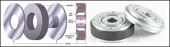 An interesting phenomenon is the increase in the
field strength of weak magnets with soft iron. Neodymium magnetic rings are
mostly only used in small earphones. Large-diameter speakers are made with
ferrite rings. This is an incomprehensible procedure, since an even stronger
magnet would be needed to move the large-diameter diaphragm. Manufacturers meet
this requirement by inserting a soft iron disc in the middle of the ferrite
ring, and forming the air gap in which the diaphragm's voice coil moves. The
field strength here is very high, because while the ferrite magnet magnetizes
the iron disc, it also mobilizes all the domains in it. Since soft iron has
more domains than ferrite, the magnet made in this way is much stronger than
the ferrite ring.
An interesting phenomenon is the increase in the
field strength of weak magnets with soft iron. Neodymium magnetic rings are
mostly only used in small earphones. Large-diameter speakers are made with
ferrite rings. This is an incomprehensible procedure, since an even stronger
magnet would be needed to move the large-diameter diaphragm. Manufacturers meet
this requirement by inserting a soft iron disc in the middle of the ferrite
ring, and forming the air gap in which the diaphragm's voice coil moves. The
field strength here is very high, because while the ferrite magnet magnetizes
the iron disc, it also mobilizes all the domains in it. Since soft iron has
more domains than ferrite, the magnet made in this way is much stronger than
the ferrite ring.
There is also a special advantage to the ring-shaped magnet. If this shape is twisted by 180° while being pressed, it becomes a Möbius shape. If this shape is wound, it radiates subatomic energy in only one direction. This way, in the case of medical use, we can exclude YIN energy from it. Its greatest advantage will be in space exploration. With this, we can make an effective antigravity engine or create artificial gravity in a spacecraft. The desired energy can be achieved by reversing the polarity of the power supply.
The super magnet cannot perform miracles. It does not magically cure us, but it speeds up the healing process. According to naturopaths, if an illness develops over a long period of time, it also takes a long time to heal. Let us not be impatient and take advantage of every opportunity to self-heal. If we are watching TV or reading, take the magnetic disc with a handle and press it on the painful part of our body. It is not necessary to completely remove the treated skin surface for the treatment. A thin shirt, T-shirt, underwear or socks can be left on without any problems. The energy radiation of the super magnet is only reduced by magnetizable metals, but even then only to a small extent. Make sure not to use the back of the device for treatment, because the other side of the magnetic disc emits Yin energy, which can trigger the diseases mentioned in the brochure. Therefore, do not use the device in bed, because if we fall asleep, one of our body parts may be in contact with this surface for hours.
The super magnet is prohibited for use by patients with fever, during pregnancy, infants or people with pacemakers. The super magnet can only be carried separately. Do not place it near watches, smartphones, magnetic tape cassettes, magnetic disks, rewritable compact disks, pen drives, memory cards, credit cards, phone cards or access cards, biometric passports, chip card ID cards, because their high field strength will damage or erase the information on them. It is also useless for mobile phones and laptops if they come close to it.
Attention! The permanent magnet is not considered a medical device. It does not replace any medical treatment or therapy, but is a supplement to them. This medical aid is primarily used to relieve pain and shorten recovery after surgery. With repeated use, it can also eliminate joint inflammation. In some cases, it promotes deep, restful sleep. However, it cannot cure chronic diseases. In case of serious symptoms, consult a doctor, because timely surgery can save our lives.
This device is easy to manufacture and cheaper to sell, if there was money for its design. The neodymium magnet is fragile and cannot withstand moisture. If we handle it a lot or if it is exposed to water for a long time, the nickel coating will come off. And the neodymium underneath will crumble. Therefore, it must be placed in a polycarbonate case. In order for the far, Yin surface to not radiate harmful energy into our hands, it must be equipped with a handle. The handle that fits the disk must be slightly raised so that it can fit under our fingers during treatment.
When choosing a magnetic disk, you should not skimp. Due to the effective treatment, a super magnet must be used. The strongest and cheapest super magnet is the N55 strength neodymium magnet. It can be purchased cheapest in the TEMU web store operating in America. Ideal diameter: 50 mm. As we have seen above, it is not necessary to use a thick magnetic disc, because a thin one is not much weaker. (The price of 5 mm and 30 mm thick magnetic discs can be found in the compressed appendix.)
The distribution and use of this cheap medical aid does not encounter any obstacles, because humanity has been using natural magnets for healing for thousands of years, which is why the authorities do not oppose its use today. They view it as medicinal herbs that have also been used for thousands of years. As we have seen above, American medical researchers have already shown what effect the Yang and Yin surfaces of permanent magnets have on the body. This simple and cheap medical device would mainly help the poor, the poor, who cannot afford the services of expensive private clinics. However, I cannot make it available to them, because I do not have the money to manufacture it.
Budapest, 2025.07.12.
![]()
DECLARATION
Anyone is free to use the information provided here. You do not need to ask permission or pay for it. However, you are joining a community of developers, which entails obligations. This obligation is the sharing of information. It is now well known that global warming is threatening climate collapse, leading to the destruction of nature. The eradication of poverty and disease cannot be postponed any longer. The messages from beyond are that knowledge is the key to our salvation. Since official science cannot solve these problems, a paradigm shift is needed. But this huge task can only be achieved through international cooperation and collective action.
Those who take part in this process cannot exclude anyone from using the results they have achieved. The additional information that they add cannot be encrypted and patented. In this way, all the results in this field, which is still unrecognised today and even cursed by scientists, will be made public. We should be compensated for this material loss by the knowledge that a paradigm shift occurs only once in the history of every civilisation. If we take part, we will have a great adventure, and later we will be proud to have taken part in the most exciting struggle of our civilisation. Those who achieve outstanding results in the next few decades will forever write their names in the history of our civilisation. Time is of the essence for us, so let’s not waste our energy on making a profit. Our lives are more important than our money. So let us not let our earthbound instincts rule us. Let us work with all those who can make a difference in this field, for the greater good. We can achieve more by working together than by developing in isolation. For our survival, we should not block the free flow of information.
Budapest, 21 January 2022.
![]()
KUN Ákos
Ó Ákos Kun
E‑mail: info@kunlibrary.net