ÁKOS KUN
Resonance frequency excitation
Motto:
You have to learn a lot to know
how little you know.
István Széchenyi

Update: December 04, 2025
This work can also be viewed in the Hungarian Electronic Library. However, the regularly updated version can only be downloaded from the websites operated by me. The development folder is not available on HEL either. Without the auxiliary files in the compressed folder, the functional description cannot be used perfectly. Path to the attached folder: https://subotronics.com → Subotronics Forum → Subotronics Laboratory → Language: ENGLISH. The HTM version can also be found on these websites. However, it only contains the operational description. Also in a hard to read form. Therefore, it is suitable for informational purposes only.
Technical description
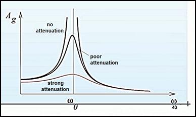
Resonance frequency excitation is a well-known phenomenon in physics. According to lexicons and textbooks, resonance is a forced vibration in which the frequency of the external forcing force is the same as the natural frequency of the vibrating system. In this case, very large amplitudes occur. The maximum position of the resonance curve is the same as the natural frequency. Every physical body has its own frequency, so it can be brought into resonance from the outside. Resonance can be induced by any physical phenomenon capable of vibration (e.g. movement, sound, light, electromagnetic wave). The best-known and most spectacular way of doing this is vibrating with sound waves. By vibrating with its own frequency, a high-rise building can be destroyed in a few minutes.
The most efficient way to induce resonance is through magnetic excitation. However, we do not yet know how to do this, because physicists deny the existence of the ether, and therefore do not try to put the activity of etherons in this direction at the service of practice. This physical phenomenon is only used by specialists and inventors working on the fringes of science, with very little efficiency. The reason for their meager results is that professional scientists classified them as quacks, charlatans, and impostors. Therefore, they do not receive financial support from anywhere for their work.
Resonance can also be induced with electrons in a manner known in electrical engineering. The use of oscillators goes back a hundred years, as old as radio. All broadcasting devices contain serial or parallel LC, RC and RLC circuits tuned to the resonance frequency. However, the use of electrons in metallic conductors stopped here. During the 200 years of electricity use, no one thought of feeding metallic conductors (e.g. filament, heating coil) at a resonant frequency. If they had done this, they would have quickly realized that at least an order of magnitude less energy is needed to achieve the desired light or heat effect. This would have required tens of power plants and power supplies, which would have been desirable mainly from an environmental point of view, but would also have had a beneficial effect on consumers' wallets. This unfortunate situation has greatly contributed to global warming, the threat of climate collapse, skyrocketing energy prices, and the resulting inflation.
Extraterrestrial civilizations watch our sufferings as a result of our negligence with compassion, but they do not interfere in our development. The intergalactic convention of the societies that have become the cosmic human type strictly prohibits the transfer of finished results and solutions to less developed worlds. Any species that violates this rule is punished by total extermination. This sentence is unappealable and unavoidable. However, targeting is not far from them. This happened to us in one case.
A few years ago, during a UFO abduction, a man from Szeged was taken by aliens. They talked about foreign technology and connections. It seemed to him that there was some kind of connection between the technologies used in different fields. They probably have a common operating mechanism, or a physical phenomenon that enables their operation that we do not know. Unfortunately, this principle was not revealed. All they said was, "It's an extremely obvious procedure that's so simple you'll never figure it out." This is not very encouraging for us. Our scientists don't deal with simple things. What is simple and easy to understand is not scientific enough. If they cannot fill their scientific theses with integral and differential equations, then they consider it beneath their dignity to deal with it. For this reason, for the time being we are only speculating as to what the obvious procedure might be. It could easily be the electrical and magnetic excitation at the resonance frequency.
At the beginning, we will try to prove the functionality of resonance frequency excitation with electrons. It was chance that led him to this possibility. My current place of residence is an almost hundred-year-old house, an emergency apartment with a kitchen and a room without comfort, in which the fittings are also in a rather bad condition. Because of this, pipe breaks are common and the building must constantly be repaired. The electrical network is also outdated. The light switches are also at least 50 years old. Because of this, their copper contacts were anodized. Where they are in contact, where they are not. The 230 volt mains voltage tries to break through this insulating layer, as a result of which the switch clicks audibly. After a few seconds, the relatively high voltage burns through the oxide layer and the lamp lights up, eliminating the contact error.
About 10 years ago, a strange thing happened. In the evening, I turned on the ceiling light in my room and there was a huge bang. All three circuit breakers in the apartment were tripped, and even the main switch of the electric clock in the hallway tripped. And a thick layer of soot was deposited in the glass casing of the burned-out light bulb. Being an electrical engineer, I found this phenomenon extremely strange. I already knew during my school studies that the filament of a light bulb wears out after a while, and approx. They burn out after 1000 hours. In the process, the tungsten spiral breaks and the glass envelope corrodes a little. During my 60 years of professional practice, I have encountered this phenomenon several times. I have already changed more than one broken light bulb because of this. Experts explain this phenomenon by the fact that the resistance of the filament continuously decreases during use. Because of this, after a while, such a large current flows through it that it burns the filament. The split filament dangles from the electrodes.[1]
Now, however, a new light bulb has broken in a rather strange way. In this case, there was no trace of the filament. Such a current passed through it that it vaporized and was deposited as a black layer on the inner surface of the bubble. This phenomenon raised my suspicion that excess energy was somehow generated here. This energy was so great that it fed back into the grid. This tripped all the overcurrent protection circuit breakers in the building. I thought for a long time about what caused this phenomenon. After a while I realized that it could be nothing but resonance. In the electrical switch with a contact fault, the mains voltage tried to break through the oxide layer of the contacts at a rate that was the same as the tungsten filament's own frequency. This created a resonance in the filament, which created an amount of free electrons that the tungsten filament could not withstand. It behaved as if thousands of volts had been applied to it. It vaporized explosively. At its own frequency, resonance can be induced even with a small amount of energy. In this case, the tungsten spiral of the light bulb or the heating element of various boiling and heating devices can be ignited.
In the case of resonance, the extra energy is created when the atoms brought into vibration shake off the electrons from their outer electron shells. In this way, approx. the number of free electrons increases by an order of magnitude. This free energy can be disconnected from the system, which reduces the electricity bill by a tenth. However, I could not test my idea because I had no money for instruments and parts. Half of my pension was not enough for that.[2] I tried to get support from millionaire individuals, banks, institutions, and large companies, but they didn't even respond. After that, I turned to the politicians. However, the heads of the ministries also called me a quack and a charlatan and told me that they do not support fraudsters. Especially not with taxpayer money.[3]
By now, however, I managed to save enough from my meager ($400) monthly pension to buy a signal generator[4]. I have a cheap Russian-made multimeter left over from my practice 40 years ago. It is not suitable for many things, but it can be used to measure current and voltage. My soldering iron still worked. All that was needed was a 100 Watt light bulb that was at home.
To perform this experiment, a signal generator, or function generator, is essential. A wide variety of signal generators are available. However, most of them are quite expensive or their service is insufficient. However, there is an exception, the JOYit signal generator of the German company known for its versatile developments. This device is cheap and does a lot for its price. It is worth ordering, because it will also come in handy for our later developments.[5] However, for those unfamiliar with the use of function generators, the fact that there are no instructions for use is a problem.[6] In the two-page brochure, only the names of the control buttons were indicated. Therefore, before starting the experiment, read the information below:
After unpacking the device, insert the plug of the mains adapter into the socket marked DC 5 V on the back of the device. Push the other end into the outlet, then turn on the device with the blue Power button. The parameters of the two channels are clearly visible on the color TFT display. (The display has a transparent film that protects it from scratches. You can peel off this plastic film by the red corner. However, this is not worth doing now. Keep it on as long as possible. Only peel it off if it becomes cloudy from scratches or fogging switch.) There is a USB-B connector on the back of the device. Through this, you can connect to the computer with the supplied cable. It is not clear for what purpose, because Windows said that it could not find a driver for it. I wrote to the manufacturer to send the driver. As usual, they didn't reply to my letter either. The device probably sends various setting parameters to the computer, which are so complicated that only the developers of the device can navigate them. For lack of a better way, let's trust that the optimal values have been set for us.
Unfortunately, the set signal shape is not displayed by the device. What we see on the display is just a symbol. It shows what kind of signal it provides (sine, square, triangle, etc.) The change in the set signal can only be examined with an oscilloscope. For this, the manufacturer included a short cable with BNC plugs at both ends. Connect one end to the output of the signal generator and the other end to the input of the oscilloscope. It does not hurt to know that the maximum load capacity of the outputs is 250 mA. Output resistance: 50 Ω. This means that this device alone is not suitable for industrial use. In order to glow high-performance heating pads, an amplifier must be connected afterwards, which can provide a current of several amperes.
The frequency counter input can measure signals produced by external devices. Measuring range 0–100 MHz. Input resistance: 1 MΩ. The maximum voltage that can be connected is 20 V. Therefore, do not use it to measure the exact value of the mains voltage frequency, because the instrument will be destroyed. After connecting the measuring cable to the Ext In input, this function cannot be used immediately. Press the Meas (Measure mode) button. Use the Func button to change the Function instruction to Counter. Moving down, we see that the control is turned OFF. Switch the Control command to ON by pressing the arrow key. Press the OK button. Now we can start measuring. Once we're done, let's set the Function statement back to Measure. (This can be done with the arrow-shaped cursor buttons.) And set the Control instruction to OFF. Since we don't want to use the function generator for that, but to generate high-frequency signals, don't touch the factory settings. To do this, let's set the outputs.
On the main menu of the display, the parameters of the two outputs can be seen one below the other. They can be activated with the CH1 and CH2 buttons. Since we only need one channel, press the CH2 button twice. The red word OFF appears on the display. Then press the CH1 button. For this, the blue ON text appears in the CH1 sector. After that, we can control the value of Frequency, Amplitude (output voltage), Offset, Duty and Phase (phase difference between CH1 and CH2). In order to make the settings without hindrance, activate the CH1 output. Press and hold the CH1 button until you hear a beep.
By pressing the SYS (System Setup) button, the operating mode of the signal generator can be set. If we don't understand it, let's leave the factory settings. By pressing the Mod (Modulation Mode) button, we see the parameters we have set, listed. Let's not touch that. Do not set the parameters here. It is also not advisable to change the parameters displayed by pressing the Meas (Measure Mode) button. We only need the main menu.
First, select the symbol you want to use. Press the WAWE (Wawe Mode) button. Various symbols appear on the right side of the display. You don't have to select between them by pressing the function keys, because there are many more of them than what we see on the display. We use the rotary button for this purpose. With this Sine, Square, Pulse[7], Triangle, Partial sine, CMOS (square wave shifted to positive range), DC (direct voltage which can be shifted to positive and negative range in Offset mode up to 10 V, Half sine, Two-way rectified sine wave, Ramp (step wave up ), Ramp (step wave down), Noise[8], Exponential curve-up, Exponential curve-down, Multi-Tone (tone wave), Sinc (sine wave with jump-like amplitudes)[9], Lorenz wave, Arbitrary 01-15 Arbitrary waves)[10].
The brochure says that the maximum frequency of the output signal in the case of a sine wave is 60 MHz. On the other hand, the frequency cannot be raised above 15 MHz here either. (This is the case with the cheaper Lite version.) However, this is not a problem for us, because the resonance range of the heating filaments is probably in the kHz range. After setting the waveform, set its frequency. Fortunately, you don't have to turn the dial for hours until you get from zero to 15 MHz. After a long press of the CH1 button, the range identification numbers are selected after the beep. (A red rectangle will be placed below them.) Using the right and left arrow keys, you can quickly set the exact frequency value from microhertz to megahertz.
The first character stands for microhertz, the others for millihertz. The hertz range can be set with three characters after the decimal point, the kilohertz range with the next three characters, and the megahertz range with the last two characters. The way to do this is very simple. By turning the rotary knob to the right, we increase the numerical value from 0 to 9. Scrolling backwards decreases the numerical value. In this way, all frequency values can be set with an accuracy of hundredths of a hertz. However, we first need to find the value of the heating coil's own frequency, so we need to scan the frequency ranges. First, the hertz and then the kilohertz ranges must be scanned slowly, because it takes some time for the glow to develop.
Annealing also requires voltage. Hopefully as little as possible, because if a lot is needed, the power consumption will also be high. Press the Ampl button and gradually start increasing the voltage as described above. Don't make too big jumps, because if the resonance starts, the heating coil is enough. Do not bother with the OFFS (Offset button), because we do not want to add DC voltage to the waveform. Leave the factory-set value of 0.00V. We also leave the value of Duty at the factory-set value of 50.0%. In this mode, we can change the filling factor of the waveform . At a value of 50.0%, the signal will be 50% within one period, and the pause will be 50%. As the duty value increases, the signal shape will become wider and narrower, and the subsequent pause will become narrower. If it is reduced, the signal generator will switch to pulse mode. In our case this is not the best mode, because during the long pause time the electrons recombine in the metallic conductor, which reduces the excitation efficiency.
Well, then let's start experimenting. In the absence of a laboratory, I assembled the circuit on the kitchen table. First, connect one of the measuring cables to the CH1 output. Since the function generator is set to a frequency of 10 kHz and an amplitude of 5 V after switching on, set them to 0 with the Freq and AMP buttons, as well as the arrow-shaped scroll buttons and the control button. I started the test by exciting different tungsten filament bulbs. I laid out a dozen lamps on the table, from the 2.5 V flashlight bulb to the 230 V 100 W lamp. I couldn't even flash any of them. Among the waveforms, even the DC voltage mode was not able to ignite them. So my initial enthusiasm quickly died down. I failed miserably on my first attempt.
In order to find out the cause of the error, I started measuring the voltage, current and resistance. It soon became clear that it would have been a miracle if any of the lights had lit up. I measured zero voltage and zero current on the electrodes of the light bulbs. For this, I measured the resistance of the filaments. One flashlight bulb had a resistance of 1 Ω, the other 2 Ω. Well, here's the problem. The output resistance of this signal generator is 50 Ω. connecting the 1 or 2 Ohm resistor lowered it so much that it shorted out. The only reason the generator didn't fail was because its developers equipped it with output short-circuit protection. A short-circuited power connector cannot output either voltage or current. In the case of the 60 W light bulb, the short circuit has already disappeared, because its internal resistance was 60 Ω. However, the 20 V amplitude provided by the generator could not make it flash. The voltage of 10 V in the positive and negative range of the sine wave was insufficient for this. The 250 mA load capacity of the generator was not enough to operate the 230 V light bulb. (The output voltage of the function generators is not stabilized. When loaded with a 100 Ω resistor, the 20 volt amplitude drops to 15 volts.)
It was clear that an amplifier had to be used. This is an excellent signal generator, but it can only be used for control, not for work. In my childhood, I made a lot of DIY transistor radios and amplifiers, but they were all audio frequency. Class A, B and AB amplifiers are mainly used to amplify musical tracks. Their frequency range is between 20 Hz and 20 kHz. Here, however, you need a signal amplifier from 1 Hz to at least 1 MHz. I looked around on the Internet and could not find amplifiers with acceptable parameters. Finally, I came across the American ACCEL Instruments TS250 type amplifier. The Waveform Amplifier for Function Generator produces a voltage of 65 V with a current of 6.5 A. Its output resistance is 1 Ω. Well, this is what I need, I thought to myself. However, my enthusiasm was cooled by the price of the amplifier. They asked $2,150, converted to HUF 774,000. (Since it is manufactured in a country outside the European Union, this is subject to an additional 20% customs duty.) I have never had this much money. Seeing my hopeless financial situation, I thought about giving it all up.
However, the signs encouraged me not to stop developing because there is a resonance induced by the electron flow. During my measurements, I cycled through the frequency range of the generator several times from 0.01 Hz to 15 MHz. Between 0.01 Hz and 10 Hz, the pointer of my analog instrument wobbled back and forth. Then at 3kHz I experienced something strange. At an amplitude value of 20 V of the generator, the pointer suddenly precipitated. I don't know how many V it showed, because it also cut out in the 1200 V measurement range. This phenomenon probably occurred because this Deprez meter has a resonance frequency of 3 kHz. The only reason the flywheel didn't burn out was because the 250 mA unstabilized output current of the generator wasn't enough.
Due to my sad financial situation, I was forced into a situation. Once again, it turned out that I could only rely on myself. I have to develop this amp, I have no choice. The advantage of this is that I can define its parameters, and producing it at home with my own hands will cost a hundred times more than the Americans charge for it. If it's not fit for purpose, I don't need to beg anyone to change it. Publishing it is not a problem either, because everyone does what they want with their own property. I was last involved in the development of amplifiers and power supplies in 1970. Some of them were also published in the Rádiótechnika magazine. By reviewing these, I tried to update my previous knowledge, but it was clear from the beginning that a different type of amplifier was needed. A preamplifier is not needed, because this role is performed by the output of the signal generator. This requires high voltage and high current transistors. The idea arose that a much simpler triac amplifier should be built, but the thyristor and its alternating current version, the triac, are not signal trackers. It turns on and off on the control pulse. It is not suitable for amplifying different signal shapes.
Since efficiency is very important for this mode of operation, use a switching power supply as the power source. If you want to use a ready-made power supply, it won't be difficult, because today all power supplies are switch mode. However, you won't like the price. It's the same with amplifiers. They are overpriced to say the least. It's not worth buying a low-voltage and low-current path, because we won't be able to use it for much later. If we spend money on it, buy 60 V and at least 6 A. There was a suitable one. The TDK-Lambda Z60-10-IS420 60V 10A 600W power supply would be excellent, but it had a small flaw. The price was HUF 944,915. Seeing such hair-raising prices, I decided to take a look at the second-hand market. On the Vatera.hu forum, apart from a few used things, I found a lot of new things at a surprisingly low price.
One of them is the RD6006 0-60 V 0-6 A adjustable laboratory power supply from Joy-it. Its price is only HUF 43,990. It is the same as the TDK-Lambda power supply, which costs twenty times as much. Remotely controllable, programmable, value entry via its keyboard, 9 memory slots, adjustable overcurrent and overvoltage protection, battery charging, cooperation with a computer. [11] If you find its load capacity to be low, choose the RD 6012 type. It can already deliver 12 A. Its price is HUF 59,900. If this is not enough, you can also order 24 A in the Chinese AliExpress and American Amazon.com web stores. They have the RD 6024 very cheap, but you have to wait 2 weeks for delivery, which can be 3 weeks. Nevertheless, it is worth ordering from them, because the 24 A (RD 6024) in the AliExpress online store costs less than the 6 A (RD6006) in domestic online stores. I ended up ordering from them. I paid HUF 35,700 ($100) for it. (Today you don't have to pay customs and VAT, because AliExpress has established a branch office in Luxembourg. So it is already considered a European company)
Its box takes up little space, is flat, and has a design.[12] Of course, this is not what you need to put into the Resonance Frequency Exciter, but a mounted slime plate, which is devoid of any comfort functions. We can build this already. If you don't want to bother with it, take a look around the Chinese AliExpress online store. Web: https://best.aliexpress.com Here you can order high-performance switch-mode power supplies mounted on a chipboard at fantastic prices. Enter: power supply-circuit board in the search field of the opening page. PCB-mounted power supplies of various voltages and currents cost only 14-25 dollars.[13] These half-palm-sized panels already have the switch-mode mains transformer on them. They have 4 screw clips. The mains voltage (230/110 V) must be connected to two. The other two are the stabilized DC output. The 200 - 300 W they deliver is sufficient for exciting smaller radiators.
If this power turns out to be insufficient, choose a 600 W switching current power supply, fixed. with voltage output. It costs $38. This assembled printed circuit board can no longer provide only Single, but also Dual power supply with GND point.[14] With this, we can already power a 500 W switching amplifier. (For this, a dual voltage power supply unit must be selected.) A great advantage of this power supply unit is that it also supplies a 12 V auxiliary voltage. This can be used well for our function generator used in the form of a slime-plate. If the signal generator manufacturers manage to save the square generator onto a disc the size of half a palm, then we no longer need to build a separate power supply for this.
You don't even need a complete amplifier. It is enough to have a mounted chipboard, which we will install in a plastic box together with the power supply. I also found this on the Vatera.hu internet marketplace. A dealer in Budapest sells high-quality switch-mode amplifiers in a series of a few dozen, cheaply. I chose the IRS2092S Mono power stage 500 W type. This is a mounted circuit board. It doesn't have a power supply, it doesn't have any treatment organs, it's not boxed. It only has the amplifier. The input, output, power cable must be soldered on or screwed into terminal blocks. The price is HUF 6,500 ($18 instead of $2,150). At this price, it's not worth getting started and tinkering at home. The parts would cost more than the assembled panel.
Then came the second failure. After a thorough visual inspection of the amplifier, it turned out that it must be powered by a balanced power supply. Symmetrical (dual) power supplies have three terminals, +, – and GND (Ground). For this, it is not necessary to dig a large copper plate into the ground and bring it into the device via an insulated copper cable. You don't even need to connect it to the plumbing pipes. GND is nothing but the 0 point of the power supply.) Compared to this, the power supply creates the + and – voltages. However, the RD 6024 type power supply unit I bought does not produce a symmetrical supply voltage. This is a two-pole (Single) power supply. When ordering, I was misled by the fact that it has 3 banana pods. Looking more closely, I noticed that there is a barely visible pictogram between the middle sleeve with green insulating ring and the sleeve with red insulating ring +. After obtaining the manual of the power supply unit, it turned out that the green banana sleeve is used for charging batteries. The battery must be connected between the red and green connectors, and then set the charging current with the current regulator. (This is usually 10% of the maximum current.) Then you don't have to worry about it anymore, because the charger switches off automatically when the battery is charging and the charging current drops to 10 mA. So this is a good quality, versatile power supply, but that's not what we need.
After paying the tuition fee, I now began to carefully examine the various power supply types. I found the ideal lab power supply in the AliExpress online store. The output voltage of the Chinese-made KUAIQU 120V 3A DC Power Supply Adjustable Digit Display Mini Laboratory Power Supply type three-pole symmetrical (Dual) power supply can be regulated between 0 and 120 V and can deliver 360 W of power. Its price was HUF 28,539. Studying the amplifiers mounted on the printed circuit board, it turned out that the 500 W power supply I bought in the AliExpress online store costs only HUF 2,500. The Budapest dealer also bought it from here, and then sells it with a 100% profit margin. Lesson learned: it doesn't matter who we order from. Let's order from online stores. China's AliExpress is the cheapest. The selection is huge. After a long search, we find the cheapest offer. Before ordering, take a look at the right side of the product description page and check the delivery conditions. Order only if delivery is free. For small items, the shipping cost may be five times the price of the item. (If the price is unrealistically low, the loss is compensated with a horrible shipping cost. There is also a bit of fraud involved. You don't have to pay VAT and customs duties after the shipping cost. This is beneficial for the merchant, beneficial for the buyer, but not good for the state. ) It may also happen that the delivery time is 2 months.
In September 2023, AliExpress redirected its European customers to their warehouse in the Netherlands. So now our orders are not sent to the Chinese parent company, but to their European subsidiary. This is not a problem because we get the same goods for the same price as the Chinese delivered. The problem is that the delivery is not from China, but from AliExpress's warehouse in the port of Rotterdam. Therefore, by default, the service is not in English, but in Dutch. Don't despair because of this. On the header of the AliExpress website, click on the small arrow on the right side of the flag icon. In the drop-down local menu, set the item Hungary as the delivery country. Select English in the Language selection bar. (Hungarian is not available.) Set the item HUF (Hungarian forint) in the Currency selection bar. Now we can easily order. (no need to enroll in a Dutch language course.)
If the English language is also a problem for us, please order using the Google Chrome browser. Here, the Google translation program is built into the browser. After completing the above settings, a message board will appear in the upper right corner of the AliExpress website, offering to translate the website into Hungarian. Activate the English - always be translated command, then click on the Hungarian instruction. The exact, precise translation of the web page takes place in an instant, and now we can order in Hungarian. Finally, close the message board with the X button. However, let's make sure that we continue to communicate with the store in English, because neither the Chinese nor the Dutch will learn Hungarian for our sake. It is advisable to open the notifications from the Netherlands in the Chrome browser, because the letters in our mailbox are also translated. If the message board does not appear, click on the Translate Page icon in the upper right corner of the browser. Then the missing message board appears, which translates from English to Hungarian.
If we come across a high-quality product that we like, which is sold at a discount (50-90% discount), add it to our shopping cart. If we hesitate and come back to it later, we will be surprised to find that the price has been raised. If we try to order the next day, the price will increase further. However, the price in the shopping cart does not change. If we find a cheaper or better one later, we can delete it from the shopping cart at any time. (Click on the Trash icon.)
Seeing the selection of hundreds of pieces, I also realized that it is easy to get lost in this abundance. 50 years ago, I wrote my thesis on switching power supplies. At that time, this topic was still completely unknown. I found only one source work on it, a book by a Russian electrical engineer. This profession has developed a lot since then, and I was left behind. I realized that the only way to succeed in this field is to refresh my knowledge. This was not difficult, because everything you need for further training can be found on the Internet. I learned that there are two main types of switching power supplies today. One is single-stroke, the other is counter-stroke.
In the case of a single-stage switching power supply, the supply voltage after the Graetz rectifier reaches the primary winding of the high-frequency transformer in only one direction. This makes this power supply simpler and cheaper to produce. However, its efficiency is worse, so it consumes more current and dissipates more. For this reason, you need a larger transformer and heatsink. A virtual earth point is created with a resistance divider after the Graetz rectifier in the case of the counter-pulse switching power supply. This is carried on to the power supply unit and even led out to its output. (This will be the GND connection.) The advantage of this solution is that compared to the ground point, a positive and a negative half-period are generated, which are alternately connected to the primary coil of the high-frequency transformer. This will improve its efficiency. It requires a smaller transformer and heatsink. Due to the creation of a virtual ground point, its design is more complicated, but it produces less noise and the distortion of the output voltage is reduced.
It behaves like transistorized Class B amplifiers. Their no-load current is low. At rest, almost no current flows through them. The difference is that for transistor B-class power supplies, the ground point is formed in such a way that the secondary winding of the mains transformer is tapped in the middle, and this becomes the ground point. The final transistor amplifying the positive and negative half-cycles is galvanically connected to this ground point. However, switching-mode power supplies do not have an input transformer, so a virtual earth point is created there. A large current should flow through this ground point in the same way as the galvanic ground point of B-class amplifiers. However, only a few milliamperes can flow through the hundreds of kiloohm voltage dividers. This problem was solved by connecting two high-capacity (approx. 1000 microfarads) electrolytic capacitors in parallel with the voltage divider. Although capacitors do not conduct direct current, they conduct alternating current with high efficiency. Switch-mode power supplies work with alternating current due to intermittent operation. (Not with sinusoidal, but square-shaped pulses, but that doesn't matter. At a frequency of kHz, both waveforms turn into needle pulses. There is not much difference between them in terms of excitation.)
This is the reason why manufacturers do not indicate that their output is ± voltage on their ground power supplies. For the 60 V power supply, e.g. it doesn't say ±30V. In the case of real symmetrical (Dual) power supplies, both the + and - sides can be loaded. Here, however, if a direct current consumer e.g. we put a resistor and a light bulb on the + or – output and on the GND terminal, no current flows through it. GND only conducts AC current. A big advantage of creating a virtual ground point is that high-capacity capacitors reduce noise and interference. Regardless of this, switching-mode power supplies still generate high-frequency noise. Noise applied to the output voltage mainly disturbs analog devices. Shielding is useless against it, so they also cause interference. However, manufacturers do everything to eliminate this. If you look inside a computer's power supply, you will see a lot of resistors, capacitors, and inductance. Most of these are interference filters, surge arresters, and output filter coils.[15] All this does not help if there is no LC filter consisting of inductances and capacitors at the input of our analog radio. (In order to make more profit, it was saved.) In this case, after turning on our computer, the radio starts beeping, becomes noisy, and distorts. This can also cause problems with the resonant excitation of our heater, both for us and our neighbors.
What was said about switching power supplies is also true for switching amplifiers. (These are called D-class amplifiers. The designation "D" stands for digital, but these are not digital, but switch-mode amplifiers.) For this reason, the primary coil of the high-frequency transformer is excited in a back-to-back configuration. Therefore, high-power switching amplifiers can only be powered with a three-pole (with GND connection) power supply. If we connect a two-pole (single) power supply to it, it will not work. If you keep it on for a long time, it will get ruined. Professional manufacturers try to avoid this danger by writing ±60V on both the positive and negative poles. This is how they try to draw attention to the fact that a symmetrical, earthed (dual) power supply must be used here. In this case, the ± mark indicates that the voltage between the + pole and GND and the – pole and GND is 60 V. And 120V can be measured between the + and – poles.[16]
However, most of the misunderstandings that cause confusion are still to come. There are also switching mode power supplies that are actually DC/DC converters. Step up and step down converters. These produce a higher voltage from a low voltage and a lower voltage from a high voltage. Also known as buck and boost converters. These are mainly used for batteries. For powering devices that require a stabilized power supply. With boost-type power supplies, we can even double the input voltage. This is achieved by pulse width modulation (PWM). Voltage stabilization is also performed by the PWM circuit. If the load increases, the width of the square pulse on the primary winding of the high-frequency transformer increases. When the load decreases, it decreases the pulse width.
However, don't expect a miracle. If you double the output voltage, the output current is halved. It is also not possible to extract more power from this power supply than what is input. The problem with these converters is that their version mounted on a PCB looks eerily similar to real switching power supplies also mounted on a PCB. Since these are also called Power Supply, they will appear in the results list together with the real power supplies. Therefore, it is easy to order them. To avoid this danger, read the name of the power supply carefully. If it contains the words "step up" or "step down" or "buck" or "boost", we don't need that.
All of this had to be discussed in such detail in order to be able to make the right choice. It is not possible to change the order in the AliExpress online store. If it were possible, customers would change the color and shape of the clothes they ordered every day, and this is not possible in such a large store. It would take an army of people to fulfill impulsive requests. It's not easy to cancel an order either. They won't talk to us for a long time. They will say on the Chat channel that they cannot find our order number, while our ordered products are already appearing on the screen. The only viable way to cancel is to open the post-shipment notification. AliExpress regularly sends us information about where the product is. On this e-mail, click on the Check Order instruction and enter your e-mail address and password in the window that opens. The ordered product becomes visible in the next window. Click on the Returns/refunds instruction on the right. A message board appears stating that the order can only be canceled after 10 days.
After the waiting time has expired, try again and cancel your order in the next window that opens. (We activate the Returns/refunds items in each section.) After that, we get our money back after a few weeks. (If it still doesn't come after 2 month, go to our bank and they will get it back.)[17] If we changed our mind at the last moment, we can only do one thing: Don't accept the goods, send them back. If we take over, more annoyances await. The return must be requested, and the online store will only take back the goods in the original factory packaging. In addition, we have to pay the shipping cost. In the case of a return shipment, we can wait a long time for our money, because the return shipment and checking its condition will take weeks. Don't wait for the end of this. Let's order the correctly selected product again, don't waste our time. And we will get our money back at some point. Until then, let's work with our already well-selected device for the second time.
If we're really into development, we'll also need an oscilloscope. This will not be cheap, because the average price of oscilloscopes is several hundred thousand forints. However, a cheaper one is also suitable for this development. If the delivery is not urgent, order this from the AliExpress online store as well. The Hantek DSO2C10 digital oscilloscope is their cheapest, at HUF 67,216. It knows a lot for its price. Everyone who bought it praises it. It may be more beneficial for us to purchase the Hantek DSO2D15 digital oscilloscope. Its limit frequency is 150 MHz, but that is not why we will need it. This type, which costs HUF 92,122, contains[18] a function generator with a limit frequency of 25 MHz.
In terms of its cutoff frequency, the function generator is more serious than most signal generators, and it is also cheaper. In addition, we can make a wave of any shape and use it. If our development comes to fruition and the business we founded in the meantime takes off, we can also buy a Rohde & Schwarz oscilloscope. The RTE-COM4 desktop oscilloscope costs HUF 20,740,427. (Don't worry about the shipping cost, it will be free.) While I was waiting for the delivery of the new power supply, I worked on the theory of resonant frequency excitation.
We have already thought that while the efficiency of linear power supplies with a plated iron core is 40%, the efficiency of switching power supplies with a ferrite transformer core can exceed 90%. (The efficiency of transformers with a plated iron core is not bad, it can reach 95%. The majority of the loss of rather large linear power supplies is caused by the series stabilizing transistor.) For switching power supplies, voltage stabilization can be solved much more simply, with a pulse width regulator integrated circuit without loss . The most exciting question is what can be attributed to the mass reduction of more than one order of magnitude. While a traditional transformer with a 500 W plated iron core is so big and heavy that we can barely lift it, in the 450 W switching mode power supply of computers, only two approx. There is an annular ferrite iron core with a diameter of 3 cm. Is the magnetic conductivity of iron-containing ceramic ferrite that good? Not at all. The magnetic conductivity (permeability) of the plated iron core rolled from soft iron is much higher. (More than twice as much.)
So what causes the excess energy in switching power supplies? The answer to this can be found in all professional descriptions: high-frequency excitation. This is where the science of the experts stops. If we ask them why the frequent pulses cause an excess of current, they cannot answer. The explanation is not to be found in physics, but in subotronics. (Subotronics is the interaction of subatomic energy particles and electrons.) The extra energy is created by etheric particles. In the case of excitation with fast rise and fall pulses, the suddenly occurring excitation voltage tears off electrons from the outermost electron shell of the metal atoms. These electrons create the electric current. The greater the excitation pulse, i.e. the higher the frequency of the excitation current, the greater the electric current will be.
The ether intervenes in this process by filling the place of electrons torn from the outermost electron shell. The universe does not tolerate a vacuum, so it tries to fill it as soon as possible. Therefore, instead of the free electrons rushing to and fro, etheric particles (etheric ions) penetrate the metallic conductor. In the process, they often collide with atoms, and since the speed of etherons is 12 orders of magnitude higher than that of electrons, they cause a greater vibration in the atoms than the excitation pulses. This causes them to lose even more electrons. With low-frequency excitation (50 Hz supply), this phenomenon does not manifest itself perceptibly, because there is time for the electrons to rearrange themselves. However, with high-frequency excitation, this phenomenon manifests itself cumulatively. The frequency increase is limited only by the saturation of the iron core. This is 150 Hz for a plated iron core, while max. for a ferrite core. 1 MHz.
Subotronics offers the opportunity to further increase the efficiency of switching power supplies. Their efficiency can be increased well above 100%. One way to do this is through soliton excitation. A soliton is a pulse whose slope is greater than its rise time. It most closely resembles a sine wave skewed to the right. This wave can move enormous energy. So far, it has only manifested itself in nature, in the form of tsunamis. They travel hundreds of kilometers in the ocean before breaking on shallow shores and releasing their destructive energy. The tidal wave that forms on larger rivers is also a consequence of the tsunami. The secret of their steady progress is the ether. The soliton wave runs up slowly and its height suddenly decreases. After the wave height decreases like a shock, ethereal particles flow into the space thus formed. Ethereal particles quickly pushing into the wave valley push the water wave through the force of inertia, which causes it to move forward. This thrust is so great that it does not let the wave die for a long time.
Due to the limited number of free electrons in metallic conductors, the soliton wave cannot cause a destructive effect. However, it further increases the number of free electrons. Due to its recoil characteristics, it crumples the ethereal particles under it, which cannot leave the metallic conductor after the pulse has run its course and died. They remain in the material when the next excitation pulse starts and further increase the density of the etheric particles. This creates even more free electrons. However, the greatest increase can be achieved with resonant frequency excitation. If the designers were to measure the natural frequency of the toroidal transformer and set the frequency of the excitation pulses to that frequency, the atoms would start dancing madly. With this excitation method, the efficiency can even increase by an order of magnitude. We will now use this physical phenomenon for resonant frequency feeding.
Since I didn't have a dual power supply, I continued the development with a single power supply, probably an A-class switching amplifier. These amplifiers do not contain ferrite transformers. The pulses required for switching operation are generated by an integrated circuit. For this reason, they are very cheap, but they are only capable of low performance. I ordered a 60 W copy out of curiosity. The delivery time here was also very long. However, on December 18, Cainiao unexpectedly delivered the tiny amplifier promised by AliExpress much later. This matchbox-sized mini amplifier did not require a ± voltage with a GND terminal, so I was able to test it with the previously purchased single power supply. I connected a 24V power supply to the XH-M311 mini amplifier and controlled it from the headphone output of the desktop radio. Despite the purchase price of 3 euros, the manufacturer max. It promised an output power of 60 W, which it probably knew, because it thoroughly destroyed my 70 W speaker.
Well, then let's start the development that has been postponed for months. I removed the radio cable from the input of the amplifier and connected it to the output of the signal generator. I set the signal to 100 Hz. I turned on the power supply and waited for the hum of the sine wave. However, the amplifier did not even squeak. No matter what I did, I couldn't get him to speak. I then removed it from the signal generator and connected it to the headphone output of the radio. He didn't speak here either. Ruined. After a fiery investigation, it turned out that it was caused by a broken overdrive. I used the signal generator in factory settings. After switching on, the Yoy-it function generator adjusts to a sine wave with a frequency of 1 kHz and an amplitude of 5 V. I changed the frequency to 100 Hz, but I forgot about the amplitude. Since the input voltage of switching amplifiers is max. It can be 1.5 V, the triple overvoltage immediately destroyed the TPA3118 integrated audio amplifier.
 During my instrumental measurements, I experienced something strange.
I measured a negative voltage at the end of the BNC cable of the signal
generator. According to the international marking system, the red crocodile
clip should be the positive pole, and the black clip should be the negative
pole. With the BNC cable, this is just the
opposite. The metal body that plays the role of shielding is the positive. The spike in the middle is the
negative one. Fortunately, the resulting
reversed polarity did not destroy the
amplifier, because the signal generator and the amplifier were
independent devices. Reverse polarity would
only cause problems if the grounding points of the two devices were connected. (In order to avoid excitement, this is often necessary.) Fortunately, the
damage is only HUF 1,300, which does not lead to material deterioration. Having learned from this, I will take care of my amplifiers that
require ±
voltage and GND terminals. However, the dual power supply required for this
is waiting for you. AliExpress postponed
the promised 3-week delivery time to 2 months.
During my instrumental measurements, I experienced something strange.
I measured a negative voltage at the end of the BNC cable of the signal
generator. According to the international marking system, the red crocodile
clip should be the positive pole, and the black clip should be the negative
pole. With the BNC cable, this is just the
opposite. The metal body that plays the role of shielding is the positive. The spike in the middle is the
negative one. Fortunately, the resulting
reversed polarity did not destroy the
amplifier, because the signal generator and the amplifier were
independent devices. Reverse polarity would
only cause problems if the grounding points of the two devices were connected. (In order to avoid excitement, this is often necessary.) Fortunately, the
damage is only HUF 1,300, which does not lead to material deterioration. Having learned from this, I will take care of my amplifiers that
require ±
voltage and GND terminals. However, the dual power supply required for this
is waiting for you. AliExpress postponed
the promised 3-week delivery time to 2 months.
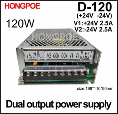
Ordering the dual power supply was not easy. The dual certification does not provide reliable support for choosing the right power supply for us either. The manufacturers also call those power supplies dual, in which they put two power supplies. Therefore, before ordering, let's take a look at its enlarged terminal block. If on e.g. you can see that it is +12 V and COM, and on the two terminals next to it, it is +5 V and COM, so these are two power supplies in one box. Manufacturers striving for precision label this type as: Dual Output Switching Power Supply. On the real dual power supply, there is not a COM or ground pictogram next to the voltage terminal, but the GND terminal, and + and – are visible on the voltage terminals (e.g. –60V, then GND, then +60V). If you want to be absolutely sure, check out the BREEZE HI-FI Audio Store offer.[19] Here, the sigle and dual power supply types can be found in one place, so we can easily choose which one we need. The power supplies they produce are mounted printed circuit (board) types. However, for development, it is advisable to purchase a boxed power supply, because it can be used later. The selection is not too big and very different.
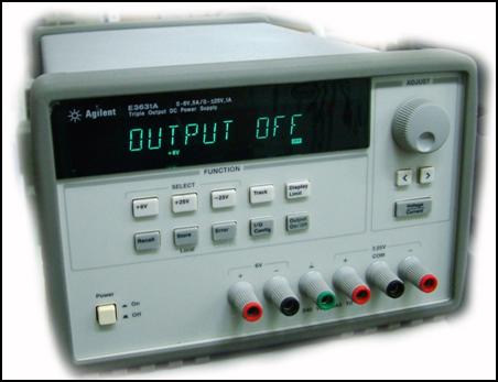
 There are also devices that contain single and dual power supplies in
a common housing. The symmetrical power supply does not have a floating GND.
Its central terminal is galvanic GND. This is indicated by the fact that it is
not marked GND, but marked COM. ±25 V means that there is a measurable
voltage of 25 V between + and COM and between – and
COM. A voltage of 50 V can be measured between the + and – terminals. Its output power is not very high, only 120 W.
(Like all Western products, the price of
this KEYSIGHT power supply unit is also quite high. Online stores sell
it for almost 2000 euros. If we can't afford this price, take a look at the AliExpress
online store.)
There are also devices that contain single and dual power supplies in
a common housing. The symmetrical power supply does not have a floating GND.
Its central terminal is galvanic GND. This is indicated by the fact that it is
not marked GND, but marked COM. ±25 V means that there is a measurable
voltage of 25 V between + and COM and between – and
COM. A voltage of 50 V can be measured between the + and – terminals. Its output power is not very high, only 120 W.
(Like all Western products, the price of
this KEYSIGHT power supply unit is also quite high. Online stores sell
it for almost 2000 euros. If we can't afford this price, take a look at the AliExpress
online store.)
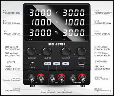
This power supply is perfectly replaced by the Chinese SPS3010-2KD Variable Dual-Channel Power Supply Lab 3-Way device. The version that can be regulated from 0 to 120V has a load capacity of 3 A, i.e. its load capacity is not 120, but 360 W. Nevertheless, it costs a tenth as much as the previous E3631A type power supply. Price HUF 80,241 (approx. 220 euros). These are two single power supplies in one house. By short-circuiting the internal + and – terminals, it can be converted into a symmetrical power supply. The shorted poles form the COM pole. In this mode, the voltage between the two extreme terminals is double, in this case max. 240 V can be measured. If the + poles and the – poles are connected, the max. 120 V, but the load capacity doubles, it will be 6 A (720W). An interesting feature of this power supply is that the power supply automatically performs the connection in series and the parallel mode with the SER and PAR push buttons.
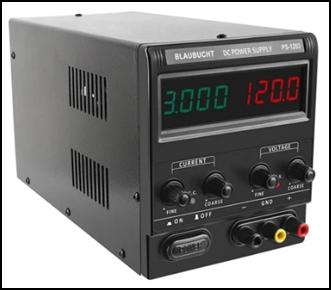
This is a great lab power supply, but not dual. If this is
what we need, choose the Blaubucht DC Power Supply PS 1203 type[20]
also in the AliExpress online store. The price of this is only 57,000 HUF (160 euros). Its voltage can also be regulated
between 0 and 120 V. Its load capacity is 3 A (360W).[21] The manufacturer does
not connect the GND and COM points to the grounding point ![]() of the
power supply. There are several reasons for this. One is the touch protection reason. Grounding the metal housing
and connecting the mains cable to the green-yellow wire is an official contact
protection regulation. So that if the device short-circuits, the operator will
not be electrocuted. The grounding cable is not routed into the ground at the
electric meter, because it would be very expensive to install it per household.
The electricity supplier takes it further to the electricity pole at the end of
the street, where a copper rod is driven into the ground and screwed to it. In
cities, in the case of underground cable
power supply, the grounding is done at the high-voltage transformers. However,
the ground is not a perfect current conductor, so ground loops can form in
sensitive circuits.
of the
power supply. There are several reasons for this. One is the touch protection reason. Grounding the metal housing
and connecting the mains cable to the green-yellow wire is an official contact
protection regulation. So that if the device short-circuits, the operator will
not be electrocuted. The grounding cable is not routed into the ground at the
electric meter, because it would be very expensive to install it per household.
The electricity supplier takes it further to the electricity pole at the end of
the street, where a copper rod is driven into the ground and screwed to it. In
cities, in the case of underground cable
power supply, the grounding is done at the high-voltage transformers. However,
the ground is not a perfect current conductor, so ground loops can form in
sensitive circuits.
 The fact that we are dealing with a real dual power supply can be
determined by measuring the voltage. A virtual GND with a floating ground
point can only conduct alternating current, not
direct current. The reason for this is that the common point of two
electrolytic capacitors connected in series forms the floating GND point. (If
we measure with a Deprez voltmeter with a small input resistance on the
terminals +
and GND, or – and
GND, it actually drains one or the other capacitor, so we measure 0
voltage. If we use a digital voltmeter, we can measure some fluctuating
voltage, because it has an internal its resistance is 20 MΩ. This
cannot reduce the voltage on the resistor divider and it cannot discharge the
buffer capacitors either, therefore, before measuring, connect a few hundred
ohm resistors between the + and GND terminals, then the – and GND terminals.) For fairly
high-frequency switching power supplies , and amplifiers, on the other hand,
the electrolytic capacitors open and play the role of the ground point. In
this way, the +
potential swings the loudspeaker membrane in one direction, while the – potential swings in the other direction. In
the same way as B and AB type amplifiers, which have a galvanic GND pole, i.e.
a symmetrical power supply is required for their operation. However, the
tension is doubled here as well. 120 V can be measured between the + and -
terminals of the ±60V
power supply.
The fact that we are dealing with a real dual power supply can be
determined by measuring the voltage. A virtual GND with a floating ground
point can only conduct alternating current, not
direct current. The reason for this is that the common point of two
electrolytic capacitors connected in series forms the floating GND point. (If
we measure with a Deprez voltmeter with a small input resistance on the
terminals +
and GND, or – and
GND, it actually drains one or the other capacitor, so we measure 0
voltage. If we use a digital voltmeter, we can measure some fluctuating
voltage, because it has an internal its resistance is 20 MΩ. This
cannot reduce the voltage on the resistor divider and it cannot discharge the
buffer capacitors either, therefore, before measuring, connect a few hundred
ohm resistors between the + and GND terminals, then the – and GND terminals.) For fairly
high-frequency switching power supplies , and amplifiers, on the other hand,
the electrolytic capacitors open and play the role of the ground point. In
this way, the +
potential swings the loudspeaker membrane in one direction, while the – potential swings in the other direction. In
the same way as B and AB type amplifiers, which have a galvanic GND pole, i.e.
a symmetrical power supply is required for their operation. However, the
tension is doubled here as well. 120 V can be measured between the + and -
terminals of the ±60V
power supply.
Therefore, the metal housing of the power supply and the load circuit are connected only if this reduces hum and excitation. The GND point is also not connected to the ground wire. Contrary to its name, GND (Ground) is not a ground point, but an internal common point of a circuit.) However, the connection of COM connectors is very effective in terms of preventing excitation. If the ESD or interference does not disappear in this way, an L-C noise filter must be used at the input of the supply voltage. This is already included several times in the power supplies. The most effective way to find out the series inductance and parallel capacitor placed after the power connectors of the load circuit is by trial and error. (Due to the high frequency, only ferrite-core inductance can be used here as well.) There are hundreds of such ferrite-core coils in the AliExpress online store, very cheaply. (Take one in which the ferrite core can be screwed in and out. That way, you don't have to try so many types.)
After the final version is made, we have to measure the inductance of the coil. Stores offer inductors in µH and mH classes. AliExpress also offers the cheapest solution for measuring inductance. The Proster BM4070 Digital LCR TESTER has a professional design. It measures inductance, capacity and resistance in a wide measurement range. Price: HUF 9,610, which is much cheaper than similar Western-made measuring instruments.[22] (For high-voltage capacitors, wait until the charge stored in them is discharged. The instrument cannot withstand a voltage higher than 36 V. If you want to measure immediately, use the included screwdriver to short-circuit its poles.)[23]
On the power supply unit of the HONGPOE D-120 type module, it is clearly visible that the manufacturer does not connect the COM point to the grounding point of the power supply unit. This is a + and – symmetrical power supply, which supplies 48 V between the V1 and V2 terminals. We can easily make a dual power supply from this power supply. For this, nothing else needs to be done than to connect the two COM terminals. (These two terminals are actually nothing but the left power supply unit – and the + terminal of the right power supply unit. To facilitate its connection, the manufacturer includes a short-circuiting shoe embedded in plastic, which just needs to be pushed onto the two terminals.)
 Interchanging the phase (L) and neutral (N) wires when operating the
module power supplies can cause malfunctions and electric shocks. (In power
supplies, the current flows from the phase wire and returns to the neutral
wire.) If the two wires are interchanged, the current flows backwards, which
makes the power supply inoperable, and
touching the phase to the common points of the circuit can also cause a
fatal electric shock. At our mains sockets, L, or the phase wire, is brown, N,
or the neutral wire, is blue, and FG, or the protective earth wire, is green
and white striped. For foreign mains sockets, L, or the phase wire, is red, N,
or the neutral wire, is black, and FG, or the protective earth wire, is white.
Interchanging the phase (L) and neutral (N) wires when operating the
module power supplies can cause malfunctions and electric shocks. (In power
supplies, the current flows from the phase wire and returns to the neutral
wire.) If the two wires are interchanged, the current flows backwards, which
makes the power supply inoperable, and
touching the phase to the common points of the circuit can also cause a
fatal electric shock. At our mains sockets, L, or the phase wire, is brown, N,
or the neutral wire, is blue, and FG, or the protective earth wire, is green
and white striped. For foreign mains sockets, L, or the phase wire, is red, N,
or the neutral wire, is black, and FG, or the protective earth wire, is white.
Since it is not stipulated in household sockets that the phase and neutral wires go to the right or left armature, when connecting the resonant frequency generator to the network, reverse polarity can easily occur. To avoid this, use a phase pencil to check which wire is the phase, and push the mains plug of the resonant frequency generator into the socket so that the connector of the plug marked with "L" is connected to the phase of the socket. (A phase pencil can be purchased inexpensively at any electrical specialist store.) After commissioning, the operator must be warned not to reverse the socket plug, and during the installation of the radiator in another room, call a specialist to check that the socket used there is connected in the correct polarity.[24]
If you want to study the spiritual world of real dual power supplies, order the two simple circuits in the attachment folder. We can measure the pre-assembled unit at several points with a voltage meter or oscilloscope. If we decide that we need this, we can DIY ourselves a real dual power supply with adjustable output voltage from the kit version. Pre-assembled and kit power supplies can be ordered inexpensively from the AliExpress online store. Measuring these makes it clear to us what the difference is between dual power supplies, dual output (two single power supplies built in a common housing), dual power supplies with a galvanic GND connector (made by connecting two single power supplies in series) and symmetrical power supplies[25] (with a galvanic GND connector power supply unit).
(Do not connect the points marked with the ![]() symbol to the
metal frame of the device or to the protective grounding connector of the mains
plug, because this can cause an earth loop, which can trigger excitation. This
is the internal earth point of the circuit and not a contact protection earth
point. In case of excitation, connect it to the internal earth point of the
load circuit .) Since the efficiency of the plated transformer is 95%, we can
safely use it to generate the input alternating voltage of small dual power
supplies. The input AC voltage should be 4V higher than the output DC voltage.
(It should not be much larger, because this turns into heat, which the small
heat sinks can no longer dissipate into the environment.)
symbol to the
metal frame of the device or to the protective grounding connector of the mains
plug, because this can cause an earth loop, which can trigger excitation. This
is the internal earth point of the circuit and not a contact protection earth
point. In case of excitation, connect it to the internal earth point of the
load circuit .) Since the efficiency of the plated transformer is 95%, we can
safely use it to generate the input alternating voltage of small dual power
supplies. The input AC voltage should be 4V higher than the output DC voltage.
(It should not be much larger, because this turns into heat, which the small
heat sinks can no longer dissipate into the environment.)
As development became more and more complex, I realized that
I couldn't get by without an oscilloscope. That's why I ordered the
aforementioned Hantek DSO2D15 digital oscilloscope on loan from a relative.
After unpacking it, it turned out that Hantek no longer provides a CD for its
oscilloscopes. Therefore, the user manual and the software required to install
it on the computer must be downloaded from its website. Click on the http://www.hantek.com/DownLoad?key=yhsc&
sid=3&word= web address to enter the company's download page. There, in
the Please select product category list, click on Digital Storage
Oscilloscope, while in the Please select product model list, click on DSO2000 Series.
There, you can download the user manual by clicking on the DSO2000
Manual item. (This can be found in the attached folder of Resonance
Frequency Excitation, in English and Hungarian.) We need the software to be
installed on the computer.
To do this, set the Digital Storage Oscilloscope item in the Please select product category list and click on the Arbitrary Waveform Editor instruction on the right side of the drop-down list. Unpack the downloaded DDS_ARB.zip folder and click on the Wave editor_Setup.exe file to install the program on your computer. (We will delete the launcher icon placed on the desktop, because we do not need this program very often.) Open the Start menu and click on the WaveEditor folder. Activate the WaveEditor icon in the drop-down folder. The Arbitrary Function Generator - Wave Editor Ver1.0.0.1 editing window opens. Here you can create any waveform, which you can then download to the Arbitrary 1, or 2, or 3, or 4 waveform items of your oscilloscope.
In the menu bar, we can see the main waveforms, which can also be found in the function generator of our oscilloscope. Therefore, there is no need to download them. These serve as a starting point here. We can redraw them to the shape we want. To do this, click on the Draw straight lines in waveform pencil icon. You can transform the main waveforms by pressing the left mouse button. If you messed it up, click on the Default Setup icon at the end of the menu bar and start the waveform conversion from the beginning. If there is only minor distortion, it does not need to be deleted. Click on the beginning of the section to be redrawn with the left mouse button and redraw the curve correctly. By clicking on the Draw smooth lines in waveform pencil icon and pressing the left mouse button, you can draw any waveform. It is not necessary to redraw all the cycles. It is enough to make one cycle. Set the Cycles selection bar to 1 item.
Once we're done with it, you can go to the oscilloscope. There, this waveform will be multiplied. Open the File menu and activate the Export as ARB instruction. After that, find your pendrive in the Windows Explorer window, select it, and save the ARB File on it. After that, connect our pen drive to the oscilloscope and copy the waveform from this device. Press the WAWE GEN button. His blue light comes on. Press the F1 menu button twice, then select the Arb1 item by scrolling the MENU button. Press the MENU rotary button. Press the F5 menu key in the Arb1 menu. The Recall field lights up and the contents of our flash drive appear on the monitor. Use the MENU knob to find the folder where we saved our waveform. Press the MENU rotary button again and turn it to the ARB FILE item. Press the MENU rotary button again. Finally, we pull the pendive from the oscilloscope, and we can use the function we drew via the GEN OUT BNC connector. (If you have accidentally pressed the F6 menu key, it is difficult to return from this mode. Neither the F1-5 keys nor the F0 key will help. Press the F6 key again.)
There are two ways to transfer the prepared ARB File to the oscilloscope. One is to install the DSO2000 Software on the computer. This program establishes the communication between the oscilloscope and the computer. (It is located in the same place as the Arbitrary Waveform Editor, only not in the right, but in the left list.) Downloading it is not easy, because downloading this 200 MB program can take up to a quarter of an hour. Starting it and installing it in the Windows Programs and Services folder does not cause any problems. Its launch is all the more so. After installation, the DigitalScope program and the WaveEditor program icon will appear on the desktop. (The DSO2000 Software also comes with the desired waveform editor, so you don't need to download it separately.) However, not everyone knows how to start it. Who still uses the spy-free and easy-to-use Windows 7 operating system, when you click on the DigitalScope launcher icon, you will receive the following answer: The program did not start because VISA32.dll is missing from the computer. You get the same response when you click on the WaveEditor launcher icon.

 Therefore, they have no other option but to download and use the
independent Arbitrary Waveform Editor program. Their activities will
not be unimpeded here either. After painstakingly creating the desired waveform, it is difficult for them to save it. The Download
waveform data to device icon at the beginning of the menu bar serves this
purpose. When you click on it, the Waveform data Download table
appears, but it only allows selection of loading to Arb1-2-3-4 positions. It only allows charging to USB
memory, but only apparently. By
clicking the Download button, the Wave editor table appears with
this message: Download Error1! Its cable transmission is hindered by the
fact that this modern oscilloscope cannot be installed on the old Windows 7
operating system. After connecting the USB cable, Windows will tell you that it
cannot find a driver for this device. Although the DSO2D15 device
appears in the Device Manager, it does not operate due to the lack of a driver.
Therefore, they have no other option but to download and use the
independent Arbitrary Waveform Editor program. Their activities will
not be unimpeded here either. After painstakingly creating the desired waveform, it is difficult for them to save it. The Download
waveform data to device icon at the beginning of the menu bar serves this
purpose. When you click on it, the Waveform data Download table
appears, but it only allows selection of loading to Arb1-2-3-4 positions. It only allows charging to USB
memory, but only apparently. By
clicking the Download button, the Wave editor table appears with
this message: Download Error1! Its cable transmission is hindered by the
fact that this modern oscilloscope cannot be installed on the old Windows 7
operating system. After connecting the USB cable, Windows will tell you that it
cannot find a driver for this device. Although the DSO2D15 device
appears in the Device Manager, it does not operate due to the lack of a driver.
This leaves nothing to do but to save with the Export as ARB command in the File menu. In this way, they can already save it to our pen drive. This method of downloading the new waveform and loading it into the oscilloscope avoids the use of a large amount of complicated software, but it still does not lead to results. The problem occurs at the very beginning of the operation. After connecting our pendrive, the oscilloscope says: Please insert the udisc. Unplug the USB cable from the computer. Thus, there is only one way to interact with the peripheral, via the USB storage device. After that, we can easily complete the upload as described above. Let's not be too happy about this either, because we will fail before the goal. After finding the ARB File and sending it to the Arb1 location by pressing the MENU button, the oscilloscope says: Recall Failed. (The oscilloscope does not communicate with previous USB 2.0 flash drives. USB 3.0 flash drives can already be opened and it looks for the folder in which the .arb file is located. However, it refuses to load.)
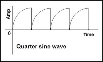
In this matter, I wrote a letter to the Hantek service department, asking for their help. As usual, they didn't reply to my letter either. They do not deal with complaints from private individuals. If I had a company, my letters would have more momentum. However, starting a company costs a lot, and I don't have the money for that. Nevertheless, I did not give up the fight. Two weeks later, I wrote to the company again. Since this is a malfunction and the warranty has not yet expired, the company would be obliged to fix the program. Now their customer service has already responded to my letter. They wrote: "Our engineers are currently analyzing the issue and will let you know as soon as there is any news." We didn't have to wait long for the answer either. The main problem was that the Quarter sine wave I was editing was not multiplying. After a period or two, there was a pause, and then the wave repeated itself. Then another pause, and so on. To my question, the developers replied that I should go to the waveform editor and click on 4096 in the menu bar. The proposal seemed good, because with 4096 repetitions the constructed wave would have become continuous. The problem was, however, that as soon as I started drawing the wave, all the shortcut icons in the menu bar went dark, so I couldn't duplicate the wave.
I informed the developers that I was unsuccessful, but they did not respond to this letter. Their knife broke into the solution of this problem. They are not alone in this. The Arbitrary editor of the German A Joy-it function generator does not work either. This device can no longer be installed on the computer. Windows 7 says „No driver found. Contact your device manufacturer for installation instructions.” I did it. They didn't reply to my letter either. After that, I looked around on the Internet. I was looking for Arbitrary function generators. Among them, the Juntek PSG9080 signal generator seemed the most promising. With this, it would probably be possible to edit any wave without hindrance. However, I can't try it because I don't have the money either. Regardless of all that, Hantek's DSO2D15 device is a very good oscilloscope. Easy to use and cheap. It also holds its own as a function generator. Factory-programmed waves can be used without hindrance. An Arbitrary function generator must be used to edit arbitrary waves.
However, editing the soliton wave will cause problems. No editing program can draw a wave that bends backwards. This is a serious problem, because Quoter sine wave and Soliton wave will play a very important role in subotronics. These waves are able to produce the most excess energy, or as esotericists say: free energy in electrical devices. Tesla used it too. He took the quarter sine wave from the commutator of a DC motor. With this, he also excited the Tesla coil, which produces millions of Volts. He had a lot of trouble with it, it was difficult to adjust, because the speed of DC motors depends to a large extent on the fluctuation of the supply voltage. He could not make a frequency generator, because a hundred years ago there were no semiconductors or even electron tubes.
During development, our work must be documented. If we want to publish our results, we need illustrative pictures. The measurement results shown by the instruments can be documented by taking photographs. The most convincing evidence is the figure shown by the oscilloscope. You don't need a camera for this, because all modern oscilloscopes can save the image on the monitor. To do this, pull out the USB cable from the computer, then insert your flash drive into the USB connector on the front panel. There are several ways to save a screenshot. Let's choose the simplest one. Press the SAVE TO USB button on the front panel. The screenshot is saved to the pendrive in PNG format. Click on it and it will appear in the Paint program. There's nothing to do with it, because you don't need to crop it around, you don't need to reduce it, because it's the size of the oscilloscope monitor. The only problem with it is the .png extension. The image in PNG format invented by Microsoft is no better than the commonly used JPEG format, it only takes up ten times as much space. Therefore, before closing the Paint editor, save the image in .jpg format.
After receiving the power supply with GND terminal and the 1000 W amplifier, as well as the oscilloscope, I was finally able to continue the development, which filled me with some concern. I was afraid that I would have to overcome more obstacles than before. I wasn't wrong. The very first step would have been a huge failure. As a result, all my circuits, components, and measuring instruments could have been destroyed. Since I don't have the money to buy new ones, this would have meant the end of the development. This danger came to light when I bought the high-performance speaker cheaply at a second-hand market. I thought I'd try it out before experimenting to see if the highly praised switching power supplies really sound that good. I personally took over the speaker from an old specialist who is now liquidating his laboratory. (According to him, none of his family members are interested in electronics, so after his death all his belongings will be thrown in the trash.)
During our professional chat, he mentioned that he designed many devices to order. Amplifiers for old rock bands and microwave devices. During the development of one of them, his device and all the gauges burned down. He doesn't know why, but I immediately realized that it was due to resonance. It hit the resonance frequency of the developed device, which created extra electrons, which increased the terminal voltage. This then fed back into the grid, cutting out all the intermediate circuits in the process. I was overcome with panic that this would happen to me too, since I would not cause the resonance randomly, but serially. What can be done about it? After much thought, I realized that what should be done is what is used in surge protection distributors. A small fusible fuse must be connected in series with the mains current, and a 250 V high-current varistor must be connected in parallel to its output.
If lightning strikes our electric meter or the high-voltage transformer installed in our residential area, the 16,000-volt primary voltage is transferred to the secondary side and burns out all devices kept in standby mode in all the apartments in the neighborhood. This will affect us financially very sensitively, because after seeing the extreme weather, the insurers announced that they would only pay in cases where the devices were operated from surge protection sockets.[26] In this case, the 16,000 volts causes the 250 V varistor to open and cause a short circuit in the outlet. This causes the 16-amp fuse to blow, and the high voltage does not come out of the socket or the distributor.[27] I have to do the same. A high-current varistor must be connected to the output of the amplifier, and before I connect it to the light bulb or the heating coil, a fusible fuse must be connected in series with it.[28]
This procedure is not a problem, but it worries me whether the amplifier can tolerate resonance frequency excitation. Producing resonance is probably not a problem, but how does an amplifier fed with ±40 or ±60 V react to this? The light bulb will only burn with full light if as many free electrons are generated in it as with mains power supply. In this case, a voltage of 230 V is generated on the two weapons. This will feed back into the amp, creating feedback that will destroy it. The only way to protect against this is to put an 80 V or 150 V varistor on its output, but this will prevent the 230 V light bulb from turning on. The low-voltage varistors stop the excitation process at the third. Connecting a diode in series with the output of the amplifier is also not a solution. The excitation takes place with a signal with a positive and negative range, and in this case the diode cuts off half the period. This can be prevented by using a two-pulse rectified sine or square wave for excitation.
So there are many questions that make this development more and more exciting. On December 28, the 1000 W dual power supply finally arrived. So I was finally able to test my 500 and 1000 W amplifiers. After measuring it, it turned out that the Tokban 1000W Switching Power Board Dual ±60V is not a real dual, but two single power supplies connected in series.[29] Manufacturers don't like floating GND power supplies, because if the negative range of the signal is smaller or larger than the positive, the floating ground point moves up and down, which causes distortion in the amplifier connected to it. This cannot happen in two power supplies connected in series, because both have their own voltage stabilizer. With this power supply, I measured a stable 60 V between the + and GND and – and GND projections. The instrument showed a voltage of 120 V between the + and – poles.
This power supply is protected against overheating, overcurrent and short circuit, so it is difficult to destroy it. Amplifiers also love it because it is not a square-wave switching device, but an LLC resonant power supply that uses a sine wave. In addition, it also provides an auxiliary voltage of ±12 V, from which a preamplifier can be powered. The 24 V measured between the + and – poles is suitable for operating a cooling fan. All in all, this HUF 21,000 power supply is too good for me. [30] It doesn't matter to the heating coil whether it vibrates with an ordinary square wave or a high-frequency sine wave. The heating element does not require an LLC resonant power supply.
First, I connected the 500W IRS2092S HIFI Digital Power Amplifier Board to it. It sounded good, but not loud enough. I thought I was looking for a stronger station on the radio. I also found a local URH transmitter that was radiating with a field strength that destroyed my 500W amplifier. It overdriven the input, causing the output stage to short out. The fan stopped and the top of one of the buffer capacitors bulged and started smoking. I bought this amplifier for double the price from a dealer in Budapest. In this case, the loss was HUF 5,500. The price of HUF 2,600 requested by AliExpress did not include the input surge protection. This power supply was also destroyed by over-control.
After that, I took out my 1000 W audio amplifier. The 1000W IRS2092S HIFI Digital Power Amplifier Board already looked like a serious amplifier.[31] It is precisely designed, and they put a relay in it, which protects the speaker from knocking when the power is turned on. (Since it's a 1000W amp, the knocker can cause the speaker diaphragm to fly out.) It also protects against the crackle that occurs when the power supply is turned off by immediately disconnecting the speaker from the amp. (The buffer capacitors in the power supply and the amplifier operate the amplifier for a few tenths of a second. In the meantime, the crackle associated with switching off could reach the speaker, which would no longer be useful for it at such a high power.) In order to do this, you need to monitor the mains voltage. Therefore, the mains voltage appearing after the Power switch of the power supply must be connected to the red terminals of the amplifier. Since we do not use this device as an audio amplifier, we also leave this terminal open.
When I tried it, this relay seemed to protect against input overvoltage because I managed to overdrive this amp as well. But it didn't fail. The relay tripped audibly and protected the output stage from a short circuit caused by over-control. In addition, this amplifier is made using imported Japanese MOS transistors and fully digital chips. As a result of its careful development, it has very little distortion. Instead of electrolytic capacitors that dry out after a few years, it contains almost eternal tantalum capacitors. Its manufacturer recommends it specifically for HiFi fans. If you buy 2 of it, you can make a stereo amplifier that can tune a studio or a concert hall.
The developers also praise this 1000 W mono amplifier. Imported MOS transistors and Japanese digital chips result in perfect frequency transfer, low distortion and stable performance. Years of product development and imported high-frequency capacitors ensure soft sound and strong bass. Overall it sounds great. All this is reflected in its price. I paid HUF 13,200 for it. Seeing these, it occurred to me again that I need this? A radiator does not need such perfect parameters. The heating coil is not interested in the frequency response of the amplifier, nor in its soft sound. However, in terms of longevity, the use of tantalum capacitors is not useless.[32] I was very careful when assembling the circuit. I protected not only the amplifier with a varistor and a fusible fuse, but also the output of the power supply and the function generator.
In addition to the too good parameters, the separate power supply and amplifier would also increase the production cost of the resonant frequency generator. This thought had already occurred to me before, so I ordered a 1000 W amplifier integrated with a power supply from the AliExpress online store. It only cost HUF 21,170, which is what I paid for a 1000 W dual power supply in Tok. The fairly large assembled panel (board) arrived at the beginning of January 2024. Several spacers and screws were added so that the panel does not touch the table, and any metal waste on it does not cause a short circuit on the printed circuit.
It also has special services. One of them, a ±15V symmetrical (dual) power supply. Its power is not very high, but it is enough to power a class AB preamplifier. This is necessary when using microphones or turntables with dynamic pickups. The 0.1 V signal of currently commonly used condenser microphones and record players used for listening to vinyl and vinyl records cannot drive an amplifier. This requires a preamplifier. We no longer have to construct the power supply required for this, because we will receive it ready.
Trying it out was easy because you didn't have to worry about connecting power cables. This type has no special parameters, but it sounded good. Its only flaw is that its heatsink-mounted fan is quite noisy. The reason for this is that it is not a ball bearing, but a cheap slide bearing. However, this can easily be helped. The power cable must be unplugged from the 24 V balance socket. By the way, there is also a version without a fan. The AIYIMA 1000W Mono Amplifier Audio Board can be ordered at this web address at the cheapest price.[33]
Unfortunately, the 1000 W amplifier integrated with the power supply did not bring me closer to my goal either. In order to achieve resonant frequency excitation, I connected the continuously tunable Joy-it signal generator to their input. A humming sound with different timbres was produced for all waveforms. They didn't break because I didn't increase the amplitude above 1.5 V here. The problem was not this, but the low output voltage of the amplifier and the high internal resistance of the load.
First, I connected a 230 V and 7 W light bulb of a sewing machine to the speaker output. Then I swept the main waves from 100 Hz to 1 MHz. After that, I tried the 230 V and 25 W lamp of the electric stove. I didn't even see a faint glow of embers. This was followed by 60 W and 100 W incandescent lamps. There was no flash here either. Then I measured the internal resistance of the lamps. The sewing machine had 500 Ω, the stove 226 Ω, and the 60 W and 100 W light bulbs 60 Ω and 35 Ω, respectively. However, audio amplifiers are not designed for such impedances. The brochure says that 1000 W is delivered when a 4 Ω speaker is connected. With an 8 Ω speaker, their output power drops to 500 W. It follows that the fairly high internal resistance of light bulbs barely gets a few watts of power. And this can't even dimly flash their filament. This is another fiasco. I've been suffering with this development for half a year, but I haven't gotten anywhere with it.
There is only one way out of this untenable situation. The load circuit must be disconnected from the supply circuit. One way to do this is with an optocoupler. But we do not manufacture multi-kilowatt optocouplers anywhere. Even if they were to produce it, it would be prohibitively expensive. The other solution is the transformer. Since high-frequency excitation is used here, only a ferrite transformer can be considered. In order to minimize the scattered magnetic field, it is advisable to use a toroidal ferrite core (ring). I visited the local parts store, where they told me that they do not sell ferrite cores or enameled copper wire. Since such transformers are used in all computer power supplies, I had an idea. I went into one of the computer repair shops and asked if they had broken computer power supplies. They said they don't have it, but they have a bad uninterruptible power supply. That's good for me too. Since it was considered E-waste, it was given away for free.
I took it apart at home and found 2 larger and several smaller interference filter ferrite rings inside. The bigger ones would be good for a transformer, but there is nothing to wind them with. I looked around the Chinese online store. They sell a lot of varieties, but more recently they give a delivery time of two months. I can't wait until the beginning of March. Browsing the Internet, I found the American TEMU online store, which is now selling its enamel cords at half price.[34] You don't have to pay any shipping costs either. I ordered 9 varieties, from 0.1 mm to 1.2 mm in diameter. In addition, they agreed on a delivery deadline of only 2 weeks. (They deliver to Europe not by cargo ship, but by plane.)
However, the method of winding caused many headaches. Since no one has ever made such a device, unlike plate transformers, there are no sizing rules or formulas for this. The optimal number of turns and wire diameter can only be determined by trial and error. Only the starting parameter is certain. The resistance of the primary coil should be 4 Ω. The wire diameter must be chosen so that the coil fits on one side of the ferrite ring. However, I could not determine the speed of the secondary winding with such certainty. To what voltage should I transform the energy of the primary coil? Does resonant frequency excitation start at 230 V or lower? It is feared that the ferrite rings with an outer diameter of 26 mm will be too small for this.
Transformer isolation will hopefully relieve my biggest fear of voltage feedback. If that happens, it will burn all my instruments and parts. In the past, cathode ray tube color TVs used 45,000 V to excite the picture tube. It didn't connect back either. It did not destroy the image and sound processing integrated circuits. The primary winding was made up of a few threaded iron-member enameled copper wires on the flyback transformer. The secondary coil was wound from hair-thin wire and embedded in resin to prevent it from falling apart. Then he was locked in a metal cage so he wouldn't get a fatal electric shock.
On January 12, I received a letter from TEMU that my order had been handed over to Magyar Posta for delivery. On the 13th, it was sent to the post office where I live, from where the postman delivered it to my house. On January 15, the small 60 W amplifiers also arrived. Due to their fragility, I immediately ordered 2 of them. I reordered them because I'm wondering if they can make at least one light bulb resonate. I was also intrigued by the fact that while the 500 and 1000 W amplifiers have a transfer frequency between 20 Hz and 20 kHz, this integrated amplifier has an upper cutoff frequency of 88 kHz. If the spiral of the radiators vibrates above 20 kHz, then this amplifier can still come in handy. I was no less interested in the fact that the output impedance of this amplifier is not between 4 and 8, but between 2 and 6 Ω, unlike the amplifiers with hundreds of watts. This means that half as much copper wire is needed for the primary winding, or the diameter of the wire can be doubled, which increases the excitation of the ferrite ring. I tried one on the same day and cut it right out. I didn't remember well how much power it requires and I connected it to 42V instead of 24V. Then the integrated amplifier started to smoke and the top burst. It's ruined too. When testing the other amplifier, I was very careful about all the details, which is why it still works.
The next day I was able to start winding the two ferrite rings, which was very difficult. Due to their small size, I could only use thin copper wire for them, which increased the risk of breakage. The 4 Ω primary coil required 8 meters of 0.2 mm diameter wire. Winding this up was quite a tedious activity. For each pass, the 8 meters of wire had to be pulled through the ring. On the first run, it became clear that this was not only tiring, but impossible. The 8-meter thin wire got tangled in several places. That's why I made a mini reel. I cut a 4 cm long piece from the end of the hurka stick (a wooden stick with a diameter of about 3 mm). I tightly wrapped 0.5 cm wide insulating tape with a thickness of 3 mm on the two ends, so that the outer threads do not slip off it, and I wound the enameled copper wire measured per meter on the spindle formed in this way. After that, it was no longer necessary to thread several meters of wire through the ferrite ring.[35] Only this small spool had to be pushed through the middle of the ring when winding each thread. (In transformer plants, the winding is done by target machines in a much simpler way.)
After the completion of the primary coil, the formation of the secondary coil on the other side caused a serious problem. How many turns should I wind on it and of what thickness of wire? In the absence of literature, there is no other option but to try. High power may be required to initiate resonant frequency excitation. However, this requires a thicker wire. However, this does not fit on the small 26 mm diameter ferrite rings. Dealers do not always specify the quality and maximum magnetization frequency of the toroid cores. Therefore, I ordered 6 types of ferrite rings with an outer diameter of 50-60 mm from AliExpress. Among them there was a cheaper one pressed from iron powder and a high-frequency version made of MnZn alloy. (The plated iron core cannot be used here, because it saturates at 150 Hz.) Switching transformers require a high-frequency ferrite iron core. The limit frequency of ferrite iron cores is max. 1 MHz. This suits us, because we expect to operate the resonant frequency generator at a few hundred kHz. In order to minimize the stray magnetic field, a toroidal iron core must be used. They can be ordered in the largest selection and at the cheapest price in the AliExpress online store.
They sell two main types. One is the low permeability iron ferrite toroid ring. (It is also called iron dust core.) The advantage is that it is cheap. The disadvantage is that its limit frequency is max. 20 kHz, which is not enough for us. It is mainly used in noise filter circuits to prevent radio frequency excitations. It is sold as an Inductor. The other is the manganese-zinc ferrite toroid ring. Its advantage is its high cut-off frequency of at least 300 kHz. (This is also used as a transformer in switching power supplies.) The disadvantage is that it costs five times as much as a ferrite ring pressed from iron powder and ceramic powder using the powder metallurgy method. (The price can be several thousand HUF, depending on the size.)
Since the TEMU warehouse sweeper sale does not last forever, it is also worth purchasing the enameled copper wire from the AliExpress web store. They are distributed in diameters from 0.1 to 5 mm, in rolls of 50 grams. It can be ordered here for the cheapest price.[36] In the case of serial production, consider the use of polyurethane-insulated copper wire. This thick insulation prevents short circuits and is easier to wind. Humid air and a wet environment will not harm it either. [37] AliExpress confirmed a delivery time of 2 months for these products as well. At this pace, this development never ends.
After completing the primer roll, I was in a big dilemma. How do I make the secondary coil? What causes the resonance frequency in metallic conductors? High current or high voltage? Since thick wire is easier to wind, I used the copper wire with a diameter of 1.2 mm first. Initially, I put enough threads on it to cover the opposite side of the ferrite ring. It only held 10 runs. Then I connected the primary coil to the output of the amplifier speaker supplemented with the power supply. The transformer load did not destroy it. I set the excitation frequency to 100 Hz and measured the secondary coil. The result was very depressing. The meter showed 0.1V. Even the 2.5 V flashlight bulb could not light this small voltage. I didn't continue winding. Another set of wires would have fit on top of the previous one, but why? I won't go anywhere with 0.2 V either. It is clear that a high voltage is required for resonant frequency excitation.
The same situation as with the electric motor invented by Newman. According to the current teaching of physics, different electrical charges accumulating on the poles of the electrical energy source create the voltage, which causes an electron flow in the connected load. The voltage at the two ends of the wire creates the electric field, and the current flowing in the wire creates the magnetic field. Voltage and current determine the field strength. This is not true. It is not the current that creates the field, but the voltage. The current that occurs during the excitation is only a forced accompaniment of the magnetic excitation. It becomes an essential companion only in the case of mains excitation voltage. Due to the fixed value of the mains voltage (220V, 380V), they can only produce a stronger motor by winding it with thicker wire, i.e. more current flows through the motor.
This forced situation was eliminated by the American inventor. He tried to reduce the current flowing through the excitation coil by winding his motor with hair-thin copper wire and exciting it with high voltage. So there was hardly any current flowing through it. His consumption was very low. Nevertheless, it was no weaker than conventional electric motors of a similar size. Since his invention was considered a device for producing free energy, the scientific community was outraged. The inventor was sidelined and his invention was never used.
This situation is familiar. They have been doing this to me for decades. However, this did not take away my enthusiasm for work. I won't give up the fight now either, then what will happen will happen. The way out was clear. For more turns and a larger coil, a larger toroidal ferrite iron core is required. However, AliExpress promised delivery by February. What should I do until then? I thought about removing the line outgoing transformer, or flyback transformer, from my old, broken cathode ray tube monitor. The secondary voltage of the series transformer of color televisions and monitors is 45,000 V. I replace the primary coil with a 4 Ω resistor, then I continue to try with this. Low excitation voltage will certainly not be a problem here. Overexcitation will probably cause the light bulbs to be destroyed one after the other.
However, this did not happen, because AliExpress unexpectedly delivered the large HUF 2,300 ferrite ring from the Choice store the next day. This toroid iron core with an outer diameter of 50 mm and a thickness of 20 mm is of high quality, but it is iron powder ferrite, which saturates above 20 kHz. Since I don't know what the resonance frequency of the heating coils is, this may also be suitable for this purpose. Due to the larger size, I wound the primary coil with a diameter of 0.3 mm, while the secondary coil with a diameter of 0.2 mm. Since the 30 mm inner diameter gave more freedom of winding, I now cut the spool from a 4 mm diameter wooden bar. (Do-it-yourself stores sell sticks of different diameters. Cut off a 6-centimeter piece from it.)
 The ideal solution for larger ferrite rings is to use a plastic
spindle. We can find it in several sizes in online stores. The attached picture
shows a spindle turned from wood. Order address[38].
For smaller ferrite rings, try this wooden spindle with a diameter of 12 mm
and a length of 50 mm.[39] The other solution
is to turn the two ends of the former wooden spindle with the manufacturer to a
diameter of 12 mm. If that doesn't work,
let's find a machine shop where they can turn it for us in minutes. The plastic spool can be ordered in the eBay
webshop. Address: https://www.ebay.com/itm/134699552428 Insert a wooden rod (e.g. the stem of a
brush) into the inner cavity for easier winding. This will make it easier to
hold the reel.
The ideal solution for larger ferrite rings is to use a plastic
spindle. We can find it in several sizes in online stores. The attached picture
shows a spindle turned from wood. Order address[38].
For smaller ferrite rings, try this wooden spindle with a diameter of 12 mm
and a length of 50 mm.[39] The other solution
is to turn the two ends of the former wooden spindle with the manufacturer to a
diameter of 12 mm. If that doesn't work,
let's find a machine shop where they can turn it for us in minutes. The plastic spool can be ordered in the eBay
webshop. Address: https://www.ebay.com/itm/134699552428 Insert a wooden rod (e.g. the stem of a
brush) into the inner cavity for easier winding. This will make it easier to
hold the reel.
 To avoid this difficult and time-consuming winding method, we can also
use a ferrite iron core of form E. As you can see in the attached picture, here
the inner core is rod-shaped. In this way, a drum-shaped coil body can be
inserted into the transformer. This reel
body can be wound quickly and precisely. Place it in a manual winding
device, and several meters of copper wire can be unhindered from the drum
placed underneath. For this type of transformer, the primary coil body must be
slid into the secondary coil body. In this arrangement, the breakdown between
the primary and secondary windings is excluded.[40]
To avoid this difficult and time-consuming winding method, we can also
use a ferrite iron core of form E. As you can see in the attached picture, here
the inner core is rod-shaped. In this way, a drum-shaped coil body can be
inserted into the transformer. This reel
body can be wound quickly and precisely. Place it in a manual winding
device, and several meters of copper wire can be unhindered from the drum
placed underneath. For this type of transformer, the primary coil body must be
slid into the secondary coil body. In this arrangement, the breakdown between
the primary and secondary windings is excluded.[40]
If we stick to the toroid-shaped iron core for the sake of the lower scattered magnetic field, then after the transformer is finished, fix both ends of the primary and secondary windings to the ferrite core with a drop of epoxy resin so that they do not slip apart. For lack of a better option, we also fix the fixing of the transformer to the textile vinyl base plate with epoxy resin. Put a drop of glue on the top and bottom of the ring, as well as on both sides, and press it to the base plate. In order to prevent crossing between the primary and secondary coils, stick a strip cut from a 2 mm thick textile vinyl sheet between them. The insulating plate glued to the center of the transformer should be at least as wide as the thickness of the transformer. (The two-component epoxy resin can also be ordered at the cheapest price in the AliExpress online store. The best-known two-component adhesive resin here is Epokitt. It is available in all DIY stores, in a 210-gram package. Drying time is 2 days.)
There are also industrial mounting solutions, but they are made of magnetizable iron sheet and are quite expensive. One is a funnel-shaped plate that sinks into the center of the ferrite ring. It can be attached to the motherboard with a screw inserted into the hole in the middle. However, this steel plate draws magnetic energy from the transformer, which weakens its efficiency. The best solution would be for this plate to be made of thermoset vinyl and the edge would also hang over the side of the transformer. This cap would not only secure, but also make the transformer vibration-proof. If a bakelite cap is used, the insulating strip between the two coils must be formed in the cap by injection molding. (In case of a large voltage difference, the insulation between the two windings is essential.)
In the case of production in smaller series, buy enameled copper wire by the kilo, not by the meter, because it is cheaper that way. At the Zotec.hu Hungarian online store, the double varnished winding wire with a diameter of 0.2 mm costs HUF 8,550 in a 1 kilogram package. The spool has 3,553 meters of wire and has a polyester-Imid-based lacquer insulation and a polyamide-Imid outer coating. It is characterized by good mechanical loadability and can be used in an extremely wide temperature range. It is heat-resistant up to 200 °C, which is very beneficial for us, because the resonant frequency generator will be placed near or behind the radiator. In the case of assembly-line production, the Chinese supply the cheapest in large quantities. The enameled copper wires produced by the Shenke company are also provided with a two-layer coating. They are insulated with polyurethane and nylon. Their base material is soft copper, so they can be easily wound. Their heat resistance is also 200 °C. Website: http://hu.shenke-gr.com/enameled-wire/enameled-copper-wire.htm (If it does not start, you must copy it into the address bar of the browser.) Request for a quote: info@zhejiangshenke.com Tel: +8615168788857
First, I tried the MKH106 small toroidal transformer coated with blue epoxy resin. His winding progressed very slowly. Even with the small spindle, I had difficulty winding the 0.1 mm diameter wire onto the 26 mm outer diameter ferrite ring. The hair-thin wire tangled four times and was excruciating to untangle. I wound all the wires delivered by TEMU, 50 meters. It was the result. With this, the amplifier was already working. First, I tried the 230 V and 7 W light bulb of the sewing machine. I set the amplitude of the function generator to only 0.5 V. Then I started to excite it with a sine wave while measuring the voltage connected to the lamp. There was a spike at 3kHz. This was probably the resonant frequency of the filament. However, the small toroidal transformer could not provide enough power to light the lamp.
I went up. To my surprise, at 12 kHz the lamp started to light up. At 17 kHz it was already at full brightness. Further increasing the frequency at 20 kHz suddenly died out. It wasn't the filament that burned out, but the overvoltage protective relay of the amplifier turned off the output stage. This protected my 1000 W amplifier integrated with the power supply from destruction. The voltage meter showed that the voltage applied to the lamp exceeded 400 V. (According to the brochure, the amplifier switches off at 500 V. Then the small red LED also goes out.) Fortunately, the 7 W light bulb was not destroyed either, it could withstand this short-term overexcitation.
After that, in order to protect the amplifier, I connected a 300 V varistor to the secondary output of the transformer, and then I put a 250 mA fuse. There was also a pitfall here. It turned out that the varistors do not open at the voltage value indicated by the manufacturers and create a short circuit in the circuit, but at twice this value. I don't know what the reason is. Having experienced this, I put a 150 V varistor in the circuit, which came into operation at 300 V. The size of the varistor doesn't matter either. High current must be used. The larger and thicker the varistor, the greater the probability that it will not be destroyed in the event of a short circuit and can be used longer. Only the fusible link needs to be replaced.
This mode of operation gave me a rather bad feeling. No resonance frequency anywhere, the lamp was on because the excitation frequency was so high above 12 kHz that it reached the power of the 50 Hz mains current. (The number of pulses increased and the pause time between them decreased.) Once the amplifier started working, I thought I would measure how efficiently the different waveforms supplied by the function generator excite the amplifier, as well as the toroidal transformer and the light bulb. I considered excitation with a sine wave as 100%. Compared to this, the saw wave (Triangle) was barely behind. The light was lit in the same way for the ascending and descending ladder (Pos-Ladder and Neg-Ladder) waves. The rising logarithmic wave (Exp-Rise) was not far behind them. However, the decaying logarithmic wave produced only 50% brightness. (The reason for this is that the free electrons in the descending branch have enough time to recombine.) For similar reasons, the rectified sine wave (half sine wave) did not excel. Only the Sinc, i.e., the impulse wave that stands out from the noise, is the past. However, a Lorenz wave similar to it caused a surprise. With it, the lamp shone just as brightly as with a sine wave.
The two-stroke rectified sine wave also behaved surprisingly. Not with the brightness it produced, because it was only 80% of the light produced by the sine wave. At this wave, the excitation frequency is halved. The lamp started to excite already at 8 kHz. It will probably do the same for the Quater sine wave, if it can be edited as an Arbitrary wave. The Multi-Tone, i.e. the wave of the audio amplifiers, on the other hand, had little effect on the lamp, even though it is similar to the Lorenz wave, only the peaks occur less often. The square wave proved to be the most effective. It excited the bulb about 20% stronger than the sine wave. (It is no coincidence that this wave is used in switching power supplies.) The CMOS wave was similarly intense. (This is nothing but a square wave raised above the t-time axis.) The worst is the noise wave. This was very disappointing to me. I thought it was mimicking ethereal noise. The lamp barely flickered from him. On closer inspection, however, this wave has a very broad frequency spectrum. Its amplitude is also constantly changing. The low-frequency and small-amplitude wave parts fall out of this type of excitation, and the rest can do almost nothing.
Finally, let's see if the efficiency of the best performing square wave changes by changing the Duty, i.e. the filling. In the default setting, Duty is 50-50%, i.e. the width of the pulse is the same as that of the pause signal. If it is increased or decreased, the brightness of the lamp will continuously decrease. And it turns off at 99% and 1%. It shines brightest with 50-50% filling. I would like to know the effect of the Quoter sine wave used by Tesla, which is a combination of a sine wave and a square wave. However, its frequency is twice those. The most exciting, however, would be the Soliton wave, if one of the signal generator manufacturers would be willing to include it among the main waves, or allow editing it as an Arbitrary wave.
Trying the ferrite transformer with an outer diameter of 50 mm did not reassure me either. It behaved essentially the same as the smaller ferrite ring. However, compared to its size, I expected more performance from it. Its sluggishness is presumably due to the fact that it is iron powder ferrite, the cutoff frequency of which is close to the frequencies I am examining. This will only become clear when the 65 mm diameter MnZn alloy ferrite ring arrives, which I don't know how I'm going to wind it yet, because I've run out of all the thin, enameled red copper wires.
The 50 mm ferrite transformer also responded to the different waves in the same way as the 26 mm version. Since this transformer was twice the size of the previous one, I thought it could flash a higher power light bulb. First I tried the 25 W lamp of the electric stove. It was only half as bright as the sewing machine light. For this, I started increasing the amplitude of the function generator up to the recommended 1.5 V. It was already burning brightly here. This was followed by the 60 W and then the 100 W incandescent lamp. They only burned with half a light. Then I further increased the amplitude of the signal emitted by the signal generator to 3 V. The amplifier was also able to withstand this.
However, the primary winding of the toroidal transformer overheated and started smoking. What should I do now? I can only reduce the current of the primary coil by increasing the number of turns of the secondary coil. However, it wouldn't fit more wires than that. For this, I switched off the transformer and galvanically connected the output of the amplifier speaker to the 100 W light bulb. The lamp was at full brightness at 16kHz and the amp didn't fail. After that, I connected 5 100 W light bulbs in parallel. They also burned with full light. The amplifier was able to withstand a load of 500 W. Thus, it became obvious that there is no need for a toroidal transformer, the switching mode excitation works without it.
After testing the light bulbs, I thought I should test how different electronic devices react to high-frequency power. They behaved very interestingly. The 3 W LED lamp with 10 kHz excitation already lit up with a terminal voltage of 120 V as well as with a voltage of 50 Hz - 230 V. LEDs love high frequency excitation. However, the nearby radio did not like it. He was terribly excited by it. Even when excited with 1 kHz, the 1 W turn signal LED lit up as if connected to mains voltage. When the frequency was increased to 2-3 kHz, it burned as brightly as the previous LED lamp consuming 3 W, and then burned out with a bang.
This was followed by the power supply for the news equipment. I connected the amplifier to the network cable of a table radio operating from a linear power supply. First I tried the sine wave set to 50 Hz. He didn't even blink. I started increasing the frequency. At 15kHz it suddenly sounded. At that time, there was 230 V on the terminals of his plug. However, it was impossible to listen because it was so loud that it drowned out the sound of all the broadcast stations. This was a big surprise. According to the literature, plate transformers saturate above 150 Hz. So how did this power supply come to life at 15kHz?
I also tested how switching power supplies react to high-frequency power. I used a power supply saved from my previous computer for this purpose. I connected another voltage meter to its 5 V output. After turning it on, the display of the voltage meter connected to the 5 V output jumped back and forth between 1 and 4 V. I also started testing with a 50 Hz sine wave. By increasing the frequency, I reached 230 V supply voltage at 16 kHz, which was measured by the other voltage meter. The voltage meter on the 5 V output continued to jump here as well. It seems that the switching mode power supply cannot handle the high frequency power supply. This completely confuses him. Fortunately, this examination did him no harm. Plugged it back into the mains and it worked perfectly again.
The electric motor test promised to be the most exciting. What does a commutator motor do when a high frequency is applied to it? Nothing. When scanning from 1kHz up, the voltage on its terminals increased steadily, but it did not respond to it. At 350 V, the amplifier was then switched off by the overvoltage protection relay. Electric motors are wound at 50 Hz. They are paralyzed at a different frequency. The same is the case with asynchronous motors. I tried to start the removed engine of a broken refrigerator in this way. It didn't budge either. The current induced by the supply voltage flowed through the coils, but the rotor could not follow the speed required by the high frequency. If this current had remained on it for a long time, its windings would have burned out.
After that, I was curious about what low-power amplifiers are capable of. Of the 3 60 W amplifiers, 1 remained, which I did not destroy. I tested its functionality as a preamplifier. He sounded good now. After that, I disconnected the speaker from it and connected the primary coil of the large ferrite transformer. I connected the 7W light bulb of the sewing machine to the secondary coil. I reduced the amplitude of the function generator to 0.5 V. I even put a 50 kΩ resistor on the input of the amplifier so that it doesn't overdrive it. Then I turned on the power. This amplifier was also destroyed in an instant. Its integrated circuit has become short-circuited. It could not handle the toroidal transformer load.
Since I definitely wanted to find out whether amplifiers with a single power supply are suitable for resonant frequency excitation, I previously ordered a similarly small 100 W amplifier. This also required a simple 24 V power supply. It worked great as an audio amplifier. It thoroughly rocked my 70W speaker. Despite its small size, it also has a volume control trimmer potentiometer, which was not necessary, because it did not break even at full volume. Then I connected the large ferrite transformer to this as well. It didn't ruin it either. I started increasing the frequency. Between 100 Hz and 22 kHz, I measured a voltage of only 5-6 V on the terminals of the light bulb. Well, that won't light up the 230 V lamp. I eliminated the ferrite transformer for this. I was convinced it was going to go broke. He could handle that too. It even responded to an increase in frequency. At 25 kHz, the voltage meter already showed 40 V. However, this was still not enough to glow the 230 V lamp. Low power amplifiers are therefore completely unsuitable for this purpose. Regardless, this is an excellent stereo amplifier. If we buy 2 pieces of it, it is perfectly suitable for tuning our room. Only the price is better than its performance. It costs only 4 euros.[41] With a cheap 24 V power supply, you can make a stereo amplifier out of it, for which Western manufacturers charge ten times as much.
However, my goal was not this, but to find the resonance frequency of the metallic conductor and reduce its current consumption. However, I have not yet achieved this. Checking the current consumption of the amplifier chain revealed that the individual components (function generator, switching power supply, amplifier) consume a lot of current. This would make the tenfold reduction in consumption that I announced impossible even if I had managed to find the resonance frequency of the lamps. After thinking carefully, what is the need for all this? Why is it necessary to excite the filament with expensive, complicated and delicate circuits? You should choose the solution that the bad light switch in my room did 10 years ago. The mains power must be interrupted. Since the mains current is quite strong, no amplifier is needed. If you chop at the right frequency, you don't even need a signal generator for excitation.
Since the mechanical chopper used by Tesla is not stable enough and requires frequent maintenance, it must be done with a switching power supply. You don't have to do anything else with it, except to remove the high-capacity buffer capacitors from its output, which smooth out the pulsating direct current. We need this pulsating square wave. This can also be connected to the load without a toroidal transformer. The mains voltage is so strong that it doesn't matter what the load's internal resistance is. The sewing machine's lamp with an internal resistance of 500 Ω glows in the same way as the 5 Ω internal resistance of a 10 kW fireplace. We should entrust a company developing switching power supplies to develop such a power supply for us. As an additional service, it would only be necessary for the frequency of current interruption to be adjustable between 100 Hz and 100 kHz with a potentiometer. There is no need for voltage regulation, because the resonance frequency does not appear suddenly, but builds up relatively slowly, so the temperature of the radiator can be controlled by underexcitation.
It would also be advisable to entrust this task to experts, because resonance frequency excitation is very disturbing to analog devices. The radio 2 meters away beeps and hisses. And a radio placed near the generator will be so noisy that no station can be heard on it. Scanning its scale, you can hear nothing but hissing and squealing. However, those with decades of experience in the development of switching power supplies are able to filter out these noises with complicated filter circuits. If we were up to it, it would take years for us to reach professionally where the greats of this field are standing. In any case, it is not worth developing something that has already been done by others. Parallel developments usually turn out to be nothing more than a waste of time and money.
A more perfect solution than the switching power supply is what the paraphenomen make. The world-famous British magician Dynamo is able to light a traditional tungsten filament light bulb without any aids. In the video http://www.figarobuveszbolt.hu/katalogs/closeup/ckorte it is clearly seen that Yin energy-emitting thumb and middle finger touch one of the poles of the light bulb, in this case the screw thread.[42] The index finger emitting Yang energy rests on the glass cover of the light bulb, and the ring finger also emitting Yang energy hangs in the air. We should ask the English paraphenomenon to help us develop. We just want to know what kind of energy flows from your fingers. To do this, you should do nothing more than touch the two crocodile clips of the oscilloscope with two fingers. First, insert a USB 3.0 or 3.1 pen drive into the USB connector on the front panel. Then press the Measure button on the front panel. After that, all the parameters of the detected wave will be visible on the screen. Not only its amplitude and frequency, but all its characteristics. After the desired wave appears on the screen, press the SAVE TO USB button. The screenshot is saved to the pen drive in PNG format. Click on it and it will appear in the Paint program. (All digital oscilloscopes are capable of taking pictures of the screen.)
If concentrated Yin or Yang energy flows from your fingers, it can only be a longitudinal wave. It is questionable whether our devices operating on the electromagnetic principle can detect purely magnetic waves. If not, we have one more reason to reconstruct the Tesla converter. The Tesla converter is the simplest, cheapest and most efficient amplifier. It produces a purely magnetic wave. This longitudinal wave makes it possible to artificially induce all esoteric phenomena. Raymond Rife's frequency generator operated with a concentrated longitudinal wave, which destroyed all microbes. A 5-minute magnetic irradiation was sufficient to cure cancer patients. Concentrated magnetic waves are also needed to make rain and control the weather. The chronovisor is based on the detection of longitudinal waves and the device enabling remote observation is also based on longitudinal waves.
Communication with extraterrestrial civilizations hundreds or thousands of light years away also requires longitudinal signal transmission. The principle of operation of anti-gravity engines is also based on magnetic waves. Electromagnetic waves only cause us harm. (Electrosmog, cancer, brain tumor, insomnia, depression.) Their main disadvantage is that they stick us to the level of technology of 100 years ago. The outdated technology that comes with it cannot solve the ever-increasing problems of our world. This requires a paradigm shift. If we do not use the escape route offered by the ether, our world will inevitably perish. Condensing etherons and gravitons can do wonders.
They don't harm our health either. Gravity is an essential part of our physical existence. Without it, we wouldn't stay on the globe, we would fly off into outer space. Like gravitons, etherons also permeate every atom of our body. So much so that we are also made of ether. They are incorporated into the etheric body we bring with us. All living beings and inanimate objects have an etheric body. The etheric body determines where and how much etheron must be concentrated in order to form the physical body. Since we are made of ether ions, the ether does not harm us, but gives us life. Together with gravitons, they fill our body with energy. Our meridian system, which collects etheric and gravitational (Yang and Yin) energy, takes care of replenishing used energy and maintaining our health. If the energy balance of our meridian system is upset due to some external harmful influence or our unhealthy lifestyle, then we get sick.
Returning to the previous topic, if it is possible to raise the excitation energy to several kilowatts, it is worth choosing the Brilagi – Electric convector heater 750/1250/2000W type among the radiators. It does not have temperature control electronics, so there is no need to separate the heating coil. (The temperature is regulated by a mechanical thermostat, (bimetal) switch. The price is only HUF 12,990.[43] Those who feel nostalgic for old, wood-burning fireplaces can find an ample version in the attachment folder. These are not much more expensive than the featureless heat radiating modules. In order to avoid the risk of fire, it is worth paying attention also for oil radiators. The temperature of these milk-sealed radiators does not exceed the temperature of central heating radiators. Therefore, it can also be installed on the wall, under the window. It will not set fire to the curtain above it.
Its output can reach up to 3 kW and it is not more expensive than thermal fireplaces. Exciting them is not a problem because they also have a bimetallic temperature controller. With this method, millions of savings can be achieved in the industry, in the monthly electricity bill. In this way, inflation resulting from the rise in energy prices can be eliminated. Bakers would certainly be happy if they could reduce the power consumption of their multi-tray electric oven to a fraction of what it used to be. It would be worth testing whether the electric arc furnaces of steelworks can be excited in this way. If so, there are some horrible savings to be made here. However, for industrial use, a much higher power supply unit must be used. These devices must also be handled with care. Do not touch them, because the 320 V peak voltage of the mains can cause a fatal electric shock. We can only touch them with the rubber gloves used by electricians![44] This device is not cheap, but it is much cheaper than the solar panels[45] installed on the roof or the heat pump system created under the building. The cost of the investment pays off in a few months, and then we can heat it almost for free for years.
After the successful development and the acquisition of a power supply with the appropriate performance, all that remains is to assemble the device. The individual units are installed in a magnetically shielded iron sheet box, not a plastic one. Fasten it to a 4-5 mm thick textile vinyl sheet, and if the developer did not do this, put it in the box bent from at least 1 mm thick galvanized iron sheet. (In this way, we also comply with the contact protection regulations.) If the power supply gets hot, ventilation holes must be drilled on the top and bottom of the iron box. If it still gets hot, a fan must be installed. For this purpose, it is advisable to use fans with a diameter of 80-120 mm used in computers. (It can be purchased cheaply in specialist stores selling electronic components. Use a ball bearing, because the plain bearing will wear out after a while and will rattle.)[46] Do not connect the metal box to the GND point of the circuits, but install a grounding clip on it. If, despite the Faraday cage shielding, interference noise occurs in our broadcasting devices, the iron box must be grounded. (The water pipe is also suitable for this, but only if it does not contain a plastic pipe section.)
In the case of fireplaces, it is worth installing the generator behind the stove so that it does not spoil the view. Fasten it to the wall. (Make two keyhole-shaped cutouts on the back and hang it on wooden screws drilled into the wall. This way, you can easily hang it up and move it to another room together with the heater. It is advisable to hide the outlet and the network cable behind the heater. Due to the high temperature, heat- resistant silicone cables up to 200°C must be used in the production of the device. This is also offered by AliExpress at the cheapest price. The resistance of the flexible cables they offer, made of hair-thin, tinned copper wire, is very low, which restrains the excitation of the components.[47] This generator's its development involved many pitfalls, but its application is now easy. If this method works, then we will be freed from this effort, because the manufacturers will install this switch-mode power supply in all electric heaters, electric stoves and water heating boilers.
It is incomprehensible why physicists have not figured out this method of excitation, why this phenomenon has not been exploited until now. Over the past 200 years, millions of electrical engineers and electrotechnicians have been active in this profession, and no one thought that the heating coils are fed with current of a higher frequency than 50 Hz. Using this physical phenomenon, the current consumption of most electrical consumers can be reduced to a fraction of the nominal current. The population uses 72% of electricity for heating and cooling, 13% for producing hot water, and 5% for baking, cooking and ironing. This is a total of 90%. Only 10% is used for lighting and operating electrical and electronic devices.
With such rates, the use of resonant frequency feeding will be a huge relief for us. The electricity bill is radically reduced from one month to the next. Cheap electricity lowers skyrocketing energy prices and the resulting inflation. In addition, cheap and clean electricity contributes greatly to stopping global warming and avoiding climate collapse. Since electricity will be the cheapest source of energy, we will no longer use fossil fuels. There will be no need for natural gas or petroleum, and we will also get rid of dangerous nuclear energy.
A wire potentiometer, not a carbon layer, should be used to control the frequency.[48] The carbon track wears off after a while, and the potentiometer will have a contact fault. The control shaft must not be led out onto the device housing. Stay in it and the end should be slotted up. Then a rotary knob, which ends in a small screwdriver, must be attached to the device. When adjusting, the extension of the control button must be inserted into the hole in front of the potentiometer so that the screwdriver fits into the slot of the potentiometer shaft. Below the rotary knob, the front panel must be calibrated for frequency. (This safety solution is necessary so that children cannot unscrew the control knobs, because in this case the heating pad will burn out.)
When using the resonance generator, first insert the control knob into the opening of the potentiometer and set it to minimum by turning it to the left. After that, connect it to the device to be excited (radiator, boiler, etc.) Slowly raise the frequency and see at which value the resonance occurs. Then increase its value until the voltage meter connected to the heating coil shows 230 V. Be careful not to overheat the heating element, as it will quickly burn out. It is advisable to heat it slightly below the operating temperature, as this will significantly extend its service life. After setting, remove the rotary knob. This procedure can only be used for appliances that do not have an electronic thermostat. In case of high-frequency power supply, the transformer of these circuits will burn out, which will destroy the circuit. In the future, this setting will not be necessary, because the manufacturers integrate the resonance frequency generator into all devices with heating pads. This will not increase the price of the device by much. This additional cost pays for itself in the first year.
The order of magnitude reduction in supply current makes it possible to bring back traditional incandescent lamps. Many people like them because the color temperature of tungsten filament lamps is most similar to sunlight. The LED lamp also consumes little electricity, but its vibrations tire the brain and cause insomnia. The eye does not perceive this vibration, but the brain does. (It is characteristic of the frequency tolerance of the LED that it can also vibrate at a frequency of GHz. However, due to its thermal inertia, the tungsten filament does not even flicker at 50 Hz.) In this case, it is not advisable to install the resonance generator in the light bulb, because there is an order of magnitude difference between the lifetimes of the two units. The excitation circuit must be installed in a porcelain socket, which is screwed into the socket of the light fixture, into which the light bulb is screwed. If the resonance frequency of the tungsten coil changes as it wears out, a small wire potentiometer must also be installed in this socket, which can be adjusted with a screwdriver.
With resonant excitation, the consumption of refrigerators and air conditioners can also be reduced. Millions of air conditioners are being bought worldwide these days due to the heat wave caused by global warming. An air conditioner is actually nothing more than a refrigerator. It differs from the kitchen refrigerator only in that it has two fans. One is in front of the cooling grid and blows the extracted cold air into the space to be cooled. The other sucks the warm air in front of the evaporator and blows it outside through a pipe. Both devices are compressors, which means they can only be operated with alternating current. In case of high-frequency excitation, the motor burns out. It cannot follow the speed dictated by the high frequency.
However, there is also another type of refrigeration equipment, the adsorption one. The essence of this system is that the coolant is not circulated by an electric motor, but by a temperature difference created by a filament. Half a century ago, it was produced in several countries, but with the decrease in the production cost of electric motors, they stopped producing it. Today, they are only produced in small sizes, for mini-studios and caravans. In narrow living spaces, the refrigerator cannot be placed in the kitchen or pantry. It must be operated in the room where the noise generated when the compressor starts and stops will wake up the sleepers.
Adsorption refrigerators are not produced on a large scale, because the production cost is much higher than the compressor version. However, the trend can be reversed if the heating coil is supplied with resonant frequency. Due to an order of magnitude lower power consumption, the higher purchase price will pay for itself in a few years. Another great advantage of the adsorption refrigerator is that it is completely silent. There is no engine noise, and there is no vibration noise associated with starting and stopping the engine. The air conditioners will also become quieter, although the whirring of the two fans will still be heard.
On the other hand, the overloading of the network, which occurs due to the fact that air conditioners are now used in almost every apartment in the southern countries, will be eliminated. The reduction in power consumption will be of great importance, especially in the case of air conditioners installed in cars. The current air conditioners consume so much electricity that the engine must be running even when the vehicle is stopped or parked, because the battery cannot handle the associated load. This in turn pollutes the air, not to mention high fuel costs. The battery will probably also be able to supply power for the air conditioner operating at the resonance frequency. The noise associated with the whirring of the engine, which disturbs both the occupants of the stopped car and the people around it, also disappears.
Budapest, February 05, 2024
![]()
Unfortunately, no progress has been made in this area in recent months. No one is willing to develop a switch mode power supply with adjustable frequency between 100 Hz and 100 kHz. However, this 1 kW signal generator would be much needed in every electronics laboratory. The British magician Dynamo could not be contacted either. According to the Internet search engine, it has its own website, but clicking on the web address www.dynamomagician.com opens a Jackpot page. I do not receive financial support from anyone. In this situation, I can only rely on myself. I am trying to find a way out of this hopeless situation. I will look into the ideas of previous inventors to see if they help. I first tried the American Newman's idea, high-voltage excitation.
As already mentioned, Newman reduced the current flowing through the excitation coil by winding his motor with hair-thin copper wire and exciting it with high voltage. So there was hardly any electricity flowing through it. Generating high voltage is no longer a problem. There is no need to remove the line-out transformer from old cathode ray televisions, because it can be purchased separately. The AliExpress online store offers Flyback transformers cheaply. After ordering them, I first tried the New Style DC6-12V High Voltage Generator, which transforms to 1 million V. The brochure specified a 12 V 1-3 A power supply as the power source. I didn't dare to use my expensive lab power supply because of possible voltage feedback. Fortunately, I kept the 12 V transformer charger of an old mobile phone with a load capacity of 1.5 A.
After connecting it, I was confident that the high-voltage generator could flash at least one 15 W light bulb. However, I have not been able to try this. According to the brochure, max. It can be operated continuously for 1 minute and will emit 1-3 cm long lightning bolts from the secondary coil. The latter statement turned out to be true. I set the distance between the ends of the secondary wires to 3 centimeters. As I plugged the power supply into the outlet, there was a huge bang and a bright discharge arc formed at the end of the secondary wires. Then a pause of a few tenths of a second, followed by another click and flash. This went on for about 15 seconds, and then the generator broke down. It got very hot, which shorted out its transformer.
I was curious as to what was in it, so I took it apart. It wasn't easy because it was surrounded by synthetic resin. It was only excavated with a hammer and chisel. A surprising sight unfolded before me. At its input I found a tiny ferrite-core transformer, the primary and secondary windings of which were wound with hair-thin, Ø 0.06 mm thick enameled copper wire. The coil body was also six-chambered, one of which was occupied by the primary coil. (In the case of high-voltage transformers, the secondary winding must be divided into chambers, because if wound in one chamber, the often 1 million volts would cause breakdowns and short circuits between the lower and upper rows.) The surprise was not caused by this, but by the output, which was 3 large foil capacitors. The strong discharge occurred when these capacitors were charged. Then there was a short pause due to reloading, and then came the next draw and snap. According to the brochure, the generator should have been able to withstand overexcitation for 1 minute, but it could not withstand even half a minute.
In this form, this device is nothing more than an undersized pulse generator. However, we need a continuously operating high-voltage transformer. This is also the case with AliExpress. The 12V 15KV High Frequency Voltage Inverter Voltage Coil Arc Generator is an ordinary ferrite core transformer for which an input voltage of DC 3.7V - 4.2V is specified. I also used an old phone battery charger for this. Nothing happened when you turned it on. The promised arc pulling was not done, which did not surprise me, because the direct voltage cannot be transformed. There is a version of this transformer complete with electronics, which chops the primary voltage and produces a square wave. Since this hadn't arrived yet, I connected a cheap signal generator with 5V amplitude, which made it work. As a precaution, I connected a 30 V varistor to its output, and then I put a 2 A fusible fuse. (If the transformer becomes short-circuited, hundreds of thousands of volts can feed back into the function generator.)
Caution was unnecessary because this tiny transformer did nothing. I first tried with the prescribed amplitude of 3.7 V, then continuously increased the excitation voltage up to 20 V. There was still no arching. For this, I boldly aimed at the 15,000 V secondary coil. The meter showed 0V. After that, I measured the resistance of the primary coil. It was 0.2 Ω. Well, that's the problem. The output resistance of the function generator is 50 Ω. 0.2 Ω practically shorted it. It's a wonder it didn't break down. Since I guessed that this small transformer would not work as expected, I also ordered the electronic version. This was confirmed by the end of April, but it arrived in mid-April. Just when the previous version failed.
The 15KV High Frequency DC High Voltage Arc Ignition Generator was supplied in kit form. It started working immediately after assembly. It drew a thin, silent arc at its outlet from a distance of 3 cm. But not for a long time. After half a minute, the heatsink of the MOSFET transistor got so hot that the power supply had to be turned off. The transformer barely warmed up here. After the heat sink cooled down, I connected the 7 W lamp of the sewing machine to the output of the generator. Although its internal resistance is 500 Ω, which means it is far from a short circuit, it did not even flash. I aimed for the secondary coil. The meter showed 5V. I increased the supply voltage to 5 V for this. At this point, the device was drawing 3 A, and its heatsink became red-hot after 10 seconds. The 15 W power was not able to flash a 7 W lamp. (After fixing it, push the transformer as far as possible from the MOSFET transistor. If they get close to each other, an arc will form between the transformer and the heatsink. Don't expect too much from this high-voltage transformer. It starts to heat up after 10 seconds, so the generator must be switched off. )
I also failed with high voltage excitation. Transformers with an output of 1 000 000 V are no longer worth trying. If the 15,000 V goes down, the 1,000,000 V, which gives an even weaker current, is also paralyzed. Using this method, the lamp could only be heated if the size of the transformer were increased fivefold. In this case, however, its current consumption would also increase fivefold. At that point, 70 W would be needed to operate the 7 W lamp. It's the same situation as when experimenting with amplifiers. Together, the amplifier, signal generator and power supply absorbed twice as much current as the light bulb consumes when connected directly to the mains.
If you think about it, this failure is not accidental. The light bulb and the heating coil are not inductive but ohmic consumers. In order for the current reduction used by Newman to occur in it, it would have to be converted into inductance. The heating coil also has some electromagnetic force field, but it is very small, since it is considered an air-core coil. Its inductance could be increased by inserting an iron core, similar to the electric motor. This would significantly increase your production cost and it wouldn't work anyway. At the high temperature caused by the heating coil, magnetization ceases. The strong thermal motion generated in the metallic conductor disperses the magnetic domains, which are thus unable to condense at the corners and create magnetic poles. Without it, there is no electromagnet. In the absence of inductance, increasing the voltage cannot reduce the current flowing through the coil, in this case the heating coil.
Nevertheless, the situation is not hopeless, because as we will see later, there are two more methods that can be used to induce resonance in ohmic consumers. One is the well-known stimulation with sound waves. This can be most effectively achieved with piezo discs, the control circuit of which would be quite complicated and expensive. Another method is the use of magnetic current. The heating coil is currently powered by electricity. The essence of this is that the voltage connected to the two ends of the metallic conductor creates an electric force field, causing the metal atoms to vibrate and electrons to be separated from their outer electron shells. These freed electrons flow through the metallic conductor, in this case the heating coil, and collide with the atoms causing great friction. The force of friction generates heat, which heats up the heating coil. However, not only free electrons can make metal atoms vibrate. In addition to ultrasound, ether can also do this. If we pass a magnetic current through the metallic conductor, the etherons cause the atoms to vibrate. Its intensity can exceed the vibrational capacity of free electrons.
This method of stimulation is only a theoretical assumption for the time being, because no one in our civilization has used this procedure yet. But it exists, because the British paraphenomenon, Dynamo, lights up the lightbulb in the same way. For this purpose, he uses a special magnetic current, the biocurrent. People familiar with natural medicine know that there are 12 meridians in the human body. Of these, 6 start and end on the toes and 6 on the fingers. Dynamo lit the light bulb with the bio-energy emanating from his fingers. This was made possible by the fact that the meridian system of paraphenomena has ten times as much energy as that of ordinary people. However, magnetic current can also be produced artificially.
The way to do this has been known for a hundred years, but until now no one cared about it. This discovery is also attributed to Tesla. Tesla not only gifted humanity with free electricity, with the converter he developed, but also with free energy. He produced this with the Tesla coil. Nobody needed that either. The profit-seeking multinational companies destroyed his converter. So did Moray, who later succeeded in reconstructing Tesla's converter. His converter was also smashed with a hammer. These two inventions could make resonant frequency excitation a success. If the production of the magnetic current is hindered, the free current produced by the converter can save this idea. In addition, in such a way that the heaters would be completely disconnected from the network. In this way, it would free people from the electricity bill, the profit hunger of energy providers and the environmental damage of power plants.
I destroyed my small multimeter during my tests. I twisted the measuring range switch button back and forth. After measuring the voltage, I wound it to measure resistance to determine the internal resistance of the coil. In the meantime, the clamp test leads remained on the circuit. The voltage introduced into the instrument destroyed the function of the resistance meter. The manufacturer draws the user's attention to the fact that when measuring resistors and capacitors, voltage must not be applied to the device. Resistance and capacitor must be measured unsoldered, with the shortest possible test lead. If it is not possible to unsolder, the device must be switched off and the capacitors inside must be discharged. Another solution is to short-circuit the resistor or capacitor to be measured with a piece of wire. However, this method falsifies the measurement. The components connected in parallel with the resistor and capacitor change its value.[49] Let's take care of our instruments![50] Before using them, it does not hurt to read the instructions for use.
Studying the Tesla coil was not a problem, because today many people deal with this magical invention. The AliExpress online store also offers dozens of smaller and larger Tesla coils. Since I guessed that it would be needed, I ordered a cheap copy and a more expensive copy. Delivery was confirmed at the end of May. It seems that this development is important to fate, because just as I stopped studying high-voltage transformers, both devices arrived the next day. 1 month earlier than promised. I was also cheated in the cheap version. The BD243 Mini Tesla Coil worked when turned on, but not the way I wanted it to. His antenna didn't throw sparks. The small Tesla coil was only able to light the tiny glow lamp at the bottom. But at least he did it for a long time. It didn't warm him up.
Then I tried to take the energy out of it. The most effective way to convert the magnetic waves formed around the secondary coil, i.e. the mini version of the Tesla tower, into electricity is to surround it with an electromagnet. Since the efficiency of iron core electromagnets is orders of magnitude higher than that of air cores, I first tried an EI 14 size mini transformer. I hung it in the air core coil. Then the glow lamp went out and the voltmeter showed zero induced voltage. Then I tried from outside. Nothing happened anyway. After that, I pulled the transformer up and down on the outside of the secondary winding. Well, a few volts of voltage was induced in it. Then I connected the primary winding of the small transformer in parallel to the secondary winding, and connected the voltmeter to the secondary winding of the transformer. This completely drained the secondary coil. The glimm lamp went out and no voltage was induced into the transformer. Finally, I touched the thin wire antenna of the secondary coil with my bare finger. At that the glimm lamp went out. It was clear that this little toy was not suitable for energy production.
Next, I unpacked the DIY Tesla Coil High Frequency HFSSTC Electronic Candle Plasma Flame. I didn't order this as a kit either, but in a module, ready assembled. I was already afraid of that, so I put on the electrician's rubber gloves ordered for the development of Resonance Frequency Excitation and turned off all my instruments and the computer. This device already creates such a strong magnetic field around itself that it induces all nearby metal objects. After protecting the output of the power supply with a varistor and a fusible fuse, I set a supply voltage of 36 V. After switching on, the device worked immediately. Pulled out of its antenna approx. It spewed sparks 3 cm long, like a candle flame. (Put a screwdriver on top of the antenna and pull out the arc immediately after switching it on, because if the energy remains in the transmitting square wave generator, the primary coil will burn out.) Be careful with the flame too, because its temperature is very high. The paper or wood held over it is immediately ignited, and the plastic is melted and then incinerated. He also heats the end of the wire and shapes it into a ball. If something catches fire nearby, switch off the power supply immediately and blow out the flame. In case of an extensive fire, cover it with a wet towel.
Unfortunately, the few-turn primary (excitation) coil got very hot even after the flame was pulled out. According to the brochure, the device can be operated continuously for half an hour. Nevertheless, after 10 seconds it gets so hot that the enamel insulation on it begins to roast. Therefore, we can only carry out our tests with it intermittently (after the coil has cooled down). We will experience interesting things. I took out my small digital multimeter and placed it next to the generator about half a meter away. Since it was still suitable for voltage measurement, I wanted to measure how much voltage the small EI 14 transformer induces. This failed, because the instrument became short-circuited when the transformer was brought close to the secondary winding. Smoke poured from it. It's completely ruined.
For this I took out my old Deprez multimeter and set its voltmeter to the highest range at 1200V. After turning on the Tesla coil, the pointer of the instrument got stuck. Judging by the amount of precipitation, at least 1500 V reached it. So I could not measure how much voltage would be induced in the small transformer. I removed the transformer from the test leads, but the instrument still hung up. It turned out that the magnetic energy emitted by the secondary coil induced such a voltage in the test leads. I thought I'd cut this tension short. I tied the two ends of the measuring tapes together. For this, they became a circular antenna. Even more voltage was applied to the instrument. Finally, I pulled the test leads out of the instrument. Then the pointer went back to zero.
Since I could not check the efficiency of the iron-core electromagnet, I took out a 15 W compact fluorescent tube. When approaching the secondary coil, it flashed at full brightness. After that, I tried a 60 W light bulb. I made a 40-turn secondary coil and soldered its beginning to one pole of the light bulb. Then I put the secondary coil on top of the primary coil as shown in the brochure. (I left the other end of the coil exposed.) The light bulb shone at full brightness. Then I reduced the number of turns of the spare coil to 20, then 10. The lamp shone just as brightly. The only change was that at 10 rounds the current consumption of the signal generator increased slightly. By the way, the secondary coil can also be placed on top of the primary. First, disconnect the exciter cable from the generator.
After that, I grounded the other free pole of the light bulb. It shone much brighter on this. To my great surprise, this did not increase the current consumption of the signal generator.[51] In this case too, free energy production takes place. This again gives physicists a nervous breakdown, who constantly complain that according to the 1st law of thermodynamics, energy cannot be created or destroyed. So if it cannot be created, then there is no free energy. Fortunately, neither the ether nor the earth knows the laws of thermodynamics. Despite the ban, they do their job. They do not obey human laws, but divine laws. They follow the laws established by the Creator. We don't know exactly what is going on. The only thing that is certain is that this phenomenon is caused by the interaction of etheric and gravitational energy.
The amount of magnetic energy emitted by a Tesla coil depends on the size of the coil. As we have seen previously, the simplest and cheapest Tesla coil could not even produce the amount of energy needed for spark generation. Its antenna could only excite and flash the glow lamp placed inside. The currently more expensive version creates sparks and turns air into plasma, and it even creates a magnetic field around itself with a diameter of at least 1 meter. To determine the efficiency of the Tesla coil, a secondary coil at least one order of magnitude larger than this is required. This is also available today. The AliExpress online store also sells a Tesla coil that weighs 40 kg and emits 1-2 meter lightning bolts. It is unlikely that buyers will line up for it, because it costs more than HUF 1 million. We can produce a similarly efficient Tesla coil for one hundredth of this price. EcoPityu explained how to do this in three videos on YouTube: https://www.youtube.com/watch?v=noJfPeZ42JI and https://www.youtube.com/watch?v=FznmIM34mJo and https://www.youtube.com/watch?v=TUGdwT2qK-Q
Tesla did not mince words. In his laboratory in Colorado Springs, he built a 130-meter-tall tower, in the vicinity of which the switched-off electric lamps were lit at a distance of several kilometers. The main problem was not caused by this, but by electrosmog. Intense magnetic stimulation produces cancerous changes in animals and plants. Tesla knew nothing about this, because he did not deal with naturopathy. Residents in the area were also more upset that the magnetic radiation interfered with the radio broadcast. (It would also have interfered with analog TV broadcasts, but there was no television at that time.) Because of this, the tower was demolished after Tesla's death. He probably measured the efficiency of his tower, because he once claimed that with one of his inventions he could produce 10 kW of energy from 1 kW.
During his public lectures in New York, London, Paris, Philadelphia, and St. Louis, he also presented a very bright lamp similar to a gas-discharge fluorescent lamp. It was characterized by the fact that only one power cord was connected to it. (This was actually an antenna that, when led into the fluorescent tube, irradiated its interior with longitudinal waves.) In his memoirs, he wrote about this tube: „I performed very interesting experiments with vibrating gas columns. I took the excitation current with a frequency of 10 kHz from a specially designed alternator. The gas discharge tube was 1 inch in diameter and 1 meter long. I capped both ends and pumped air out of it until the discharge started. Later it turned out that it is better to work with only one electrode." He was also able to generate energy with this pipe. He once said that the greatest invention of his life was a tube from which a lot of energy could be extracted. From the detailed description, it can be concluded that this tube was actually a Tesla coil.
We can also manufacture such a tube from an ordinary fluorescent tube. For this, nothing else should be done than to introduce the antenna of the secondary coil into the fluorescent tube. Then one could measure how much "a lot" of energy actually is. The "specially designed alternator" must have been a special design, because in Tesla's time there were no transistors or integrated circuits. Today, however, producing a signal generator that emits a square wave is almost child's play. A circuit consisting of an NE555 integrated circuit and a grounded-collector MOSFET power transistor at the end can easily perform this task. (We use the square generator designed by EcoPityu.)
We can also try to extract energy from the Tesla coil in another way. I could not determine how much voltage can be extracted from the iron core electromagnet placed near the secondary coil, because there is no instrument with which we could measure the induced voltage. I could not measure the induced current either, because the current induced in the test leads falsifies the measurement. For this reason, the efficiency of the small transformer placed in the secondary winding could not be measured. However, the energy extracted from the Tesla coil can be measured indirectly. Not with an instrument, but with a load. I first tried the small EI 14 permalloy transformer. Now I did not connect an instrument to the coil of the primer, but the tiny 7 W lamp of the sewing machine. I plugged the small transformer inside the secondary coil and turned on the generator. The lamp did not flash. I removed the transformer from the secondary coil. The fire was hot. The coil excited it intensely, but it could not induce enough energy to flash the lamp.
It seems that for this mode of excitation it is not the permeability of the electromagnet that matters, but the surface of the coil. An air-core coil can only transfer energy to another air-core coil with sufficient efficiency. Therefore, I wound a 12 mm diameter plastic pipe with as many turns as there were on the secondary coil and inserted it inside. I soldered the 60-W light bulb to the two ends. After switching on the generator, the lamp was fully illuminated. I soldered the end and pinched the ground wire. It shone even brighter at this. I repeated the same with an air-core coil wound on a 30 mm diameter plastic tube, which I placed on the secondary coil from the outside. The lamp behaved similarly. There seems to be no difference between external and internal excitation. However, it is a big mystery how Tesla extracted so much energy from his fluorescent tubes, if at all.
The next test was to connect a light bulb to the antenna of the secondary coil and to the beginning of the coil. At this point, the sparking stopped and the secondary winding was transformed into an ordinary transformer. To a high voltage transformer. In this regard, the working mechanism of the Tesla coil is a big mystery. According to the expert opinion voiced by esotericists, the Tesla coil decouples the energy from the ether. This is not the case, because energy particles cannot be used up, they can only be put to work. For this, it would have to be broken down into smaller particles, and there are no smaller particles in the universe than ether ions and gravitons. We can easily convert matter into energy, but there is nothing to convert energy into. Therefore, it cannot be used or consumed.
So there is no energy release, the free energy is generated in the secondary coil with the help of the ether. It takes place in the same way as in switching power supplies, only on a larger scale. The spark flame produced by the Tesla coil is nothing but a corona discharge. Since there is no end of the coil nearby to arc to, a corona discharge occurs. A discharge occurs at the end of the secondary winding of high-voltage transformers above a certain voltage level.
The same thing happens in the Tesla coil. Since here the other pole of the secondary coil is far away, at the bottom of the coil body, the discharge remains only radiation, which creates a candle flame-like plasma. For this, of course, a much higher voltage must be excited in the winding than in the secondary winding of high-voltage transformers. Strong excitation creates a strong electric field around it. In this case, the end of the coil was connected to a pointed metal object, from which free electrons escape into the air, where they collide with the gas molecules of the air and ionize their atoms. Together, they form a spectacular, candle-like plume. Moving away from the antenna, the electric field strength decreases, the free electrons are no longer able to ionize and transform the gas molecules of the air into plasma. However, the electric field does not disappear, but turns into electrosmog.
During the corona discharge, the free electrons created by the ether are not used up. At the end of the coil, they pile up and look for the other pole on which to discharge. Meanwhile, they are compacted. Due to their large number, their electrical radiation increases to a great extent, which ionizes the gas molecules of the air. This process is called a silent discharge by experts, but it is not. When discharging, there is an arc pull accompanied by a loud bang. The free electrons are then returned to the metallic conductor, in this case the secondary coil, and the discharge continues until the exciter or secondary coil overheats. Then the enamel insulation burns off them, a short circuit occurs, and the coils start to smoke. If overcurrent protection is not built into the system, this process can also cause a fire.
If you want to study the psyche and efficiency of the Tesla coil, don't experiment with small devices, because you won't get very far with them. Let's carefully watch EcoPityu's three videos and build this. There is no need for the expensive winding machine he uses, because we can wind the relatively thick enameled copper wire onto the textile-vinyl pipe by hand. (The Chinese use a porcelain coil body for the secondary winding. Porcelain can withstand even more heat than vinyl and won't catch fire.) Those with a DIY background will have no problem building a quad generator. Make sure that the two coils are wound in the same direction. In the case of winding in opposite directions, the magnetic fields of the two coils excite each other.
In order for the ether to fulfill its role as a free electron generator with high efficiency, it needs a large surface area. It can only generate a small amount of energy in a small coil of thin wire. Therefore, it would be advisable to make a solenoid at least 2 meters long, with a large diameter. A coil with a smaller diameter must be placed inside it, and a coil with a larger diameter around it. Here, don't forget about the same winding direction of the coils. If we did not pay attention to this, pull out the coil that produces little energy and put it back in reverse. After inserting the inner and outer coils, the corona discharge is eliminated because these coils absorb the energy. There is no need for arcing with a screwdriver either, because the coils perform the role of energy discharge. In order to avoid arcing and the resulting short circuit, there should be a distance of at least 1 cm between the individual coils.
Then you have to measure how much power the inner and outer coil deliver.[52] (Unload the two coils at the same time.) Add the two values, then calculate the current consumption of the excitation generator. (This will not be difficult. Multiply the set supply voltage value by the current flowing from the power supply.) If the power produced is much higher than the power used, then the Tesla coil is truly a free energy generating device. If not, it's just a high-powered electrosmog generator.
Scientists keep saying that they do not accept his esoteric claims and results because they cannot be repeated. This experiment can be done by anyone at any time. So we can finally put an end to this debate. If the measurements do not show excess energy, esotericists can still refer to the fact that Tesla's tower was 130 meters high. However, such a tall tower cannot be erected in any household, nor can such large energy-generating structures be erected at the end of streets. Thus, if the 2-meter tower does not bring the desired success, then another way to generate free energy must be found.
If this device goes into production, we can protect ourselves against EMF radiation by enclosing the Tesla coil in a box made of MU plate. It probably needs to be grounded. During development, don't forget about grounding, because this can greatly increase the efficiency of the device. As grounding, we can use the water pipe or the surface of the gas pipe polished to a metal finish. If there are no water or gas pipes nearby, we can also use the grounding pole of the mains socket during development. Clip the end of the wire to one of the ground terminals of the socket. The MU plate shielding also makes it clear what kind of energy the Tesla coil emits. Purely magnetic or electromagnetic. In my experiments it did not attract any of the tongues of the compass. If the noise stops, then it is an electric radiator. If not, then we will be in trouble, because the magnetic radiation is not shielded by anything.
In this case, we will need protective clothing if we don't want to end up in a cancer hospital. This is none other than the suba (fur turned inside out) recommended in the description of the Antigravity engine. Árpád Bóday's son also died of cancer. After his father died of a sudden illness, Jr. Árpád Bóday took over his role.[53] With years of hard work, he succeeded in reproducing the free energy utilization structures and even created a new device, the reflex resonance transformer. This surplus energy generating circuit containing permanent magnets and coils was also shown on television.
After that, he had stomach cramps. He was initially treated for an upset stomach, but later found out that he had cancer. After the removal of the malignant tumor, chemotherapy followed with the usual malaise, which prevented him from working. After six months of suffering, he turned to a Russian naturopath, who completely cured him. In the spring of 2000, all his findings were negative, so he started working again. However, after a few months, he became ill. He began to lose weight rapidly, his skin became pale, and he could barely speak. His relapsed cancer took him to the grave. The most common disease caused by magnetic radiation is blood cancer (leukemia). Sheep hair is the only way to protect against magnetic rays. This does not shade the subatomic energy particles either, because the etheric and gravitational waves penetrate all matter. However, the fine fibers of sheep hair scatter the magnetic radiation, so it cannot penetrate the body.
The design of the laboratory will also cause quite a bit of trouble. If we want to deal with the reconstruction of each of the seven inventions in the Kun Electronic Library, we must also protect ourselves against concentrated gravitational radiation. This seeps into the walls and furniture and after a while reaches a concentration that causes spontaneous combustion. This is why our laboratory is burning down. Therefore, we have to build a laboratory that does not contain flammable material. Our situation becomes even more difficult if we also deal with the development of anti-gravity engines. In this case, the laboratory must not contain iron or even iron-containing instruments. The strong etheric magnetic radiation rips the iron pipes from the wall, carries with it the iron-containing instruments stored on the shelves, and the tools on the table. It is advisable to install aluminum doors and windows, and the locking mechanisms must be made of bronze. And the start of the engine tears through the ceiling. If it looks like it will start, take it out into the yard and start it by remote control.
These dangers do not threaten me for the time being, because my meager pension of 400 euros is not even enough to buy instruments and parts for these developments. If I don't get support from anyone, I will have to stop doing esoteric developments for good. However, I have many ideas and suggestions, which I will take with me to the grave in the absence of interest and help. If their money is more important to our civilization than their lives, then let the world perish. A civilization that doesn't care about its future, and even increases the destruction of nature with its hedonistic lifestyle, deserves to be wiped off the face of the Earth. Our place will be taken by a more viable civilization, which will protect its environment with great care, because it will be aware that nature cannot be extorted, squeezed to the extreme, but must be lived in harmony with it.
Budapest, May 5, 2024
![]()
Unfortunately, no one has built the 2-meter-high Tesla tower
that I suggested, so we cannot measure its efficiency. However, high-performance
Tesla coils are proliferating on the Internet.
Many of them have been commercially available. You can choose from
dozens in the AliExpress store. The
largest exceeds 2 meters in height and
emits 1.5-meter-long lightning bolts. They cost several hundred
thousand forints. Some of them have also been built with solenoid coils
around them. However,  they do not state how much energy
can be extracted from this. It is probably less than the excitation energy. If much more energy had been extracted from it, it would
have become a world sensation and would have been sold as a free energy
generator. Tesla's tower also consumed an
enormous amount of energy. According to his diary, sparks and
lightning bolts of 2,030 meters jumped out of his 130-meter-high tower in his
laboratory in Colorado Springs. This required
so much electricity that it overloaded the town's generator, which broke down and caught fire. Colorado Springs
was plunged into darkness for days.
Tesla had to have the town's generator repaired at his own expense. He
did not use his tower to generate free energy. He created this structure so
that he could supply the area with energy wirelessly. However, he did not think
that the electromagnetic waves scattered into the air create electrosmog,
which causes blood cancer in the body.
they do not state how much energy
can be extracted from this. It is probably less than the excitation energy. If much more energy had been extracted from it, it would
have become a world sensation and would have been sold as a free energy
generator. Tesla's tower also consumed an
enormous amount of energy. According to his diary, sparks and
lightning bolts of 2,030 meters jumped out of his 130-meter-high tower in his
laboratory in Colorado Springs. This required
so much electricity that it overloaded the town's generator, which broke down and caught fire. Colorado Springs
was plunged into darkness for days.
Tesla had to have the town's generator repaired at his own expense. He
did not use his tower to generate free energy. He created this structure so
that he could supply the area with energy wirelessly. However, he did not think
that the electromagnetic waves scattered into the air create electrosmog,
which causes blood cancer in the body.
So it is almost certain that we cannot obtain free energy this way either. In the above, it turned out that a significant amount of free electrons can be generated by exciting the atoms of metallic conductors, but this is only enough to increase efficiency. With high-frequency excitation, we only achieved the following: we increased the efficiency of our linear power supplies from 40% to 95%. In addition, the size of the transformer in switched-mode power supplies has been reduced by a hundredth, and with it its price. However, excess current cannot be produced by electron excitation. The Tesla converter is capable of this, but only by feeding the excess energy generated by the resonant frequency excitation of the transformers into increasingly larger transformers in 10 stages. The negative internal resistance of the electron tube used for coupling also contributes to increasing the efficiency, which produces additional free energy. However, no one is willing to manufacture the diode and electron tube necessary for its reconstruction.
A way out of this situation must be found urgently, because if we do not switch to completely pollution-free green energy, global warming will destroy our world. Due to the increasingly unbearable heat and extreme weather it causes, agricultural crops will wither, forests will catch fire, and our houses will also go up in flames. In the end, we too will burn alive. (According to extraterrestrial civilizations, we will be fried in a few years.) Those living in countries spared by drought will not survive either. They will be destroyed by mudslides caused by flash floods and landslides triggered by hurricanes. (The inhabitants of the province of Valencia in Spain have already experienced how this happens. More than 220 people drowned in the mud, and the material damage was enormous. Before that, Hurricane Helen in America caused $400 billion in damage. The number of victims here was more than 200.) The intensity and extent of weather extremes will increase in the future. It will affect everyone in some form. Energy generation equipment will have to be installed at the consumer's site, eliminating the need for power plants, high-voltage transmission lines, and energy suppliers. This will make electricity available to everyone for free.
It wouldn't hurt if the device that produces free energy were cheaper and more efficient than the Tesla converter. However, this would require much more efficient particles than free electrons to work. We don't have to think long about what that would be, because domains immediately come to mind from our school studies. According to Dirac, the charge of magnetic monopoles is nearly seventy times the electric charge. This nearly two orders of magnitude greater energy would have to be released from metallic materials with the help of domains.
Domains are regions in ferromagnetic materials (mostly iron) in which the dipoles are arranged in parallel. Due to their random distribution of directions, their magnetic moments cancel each other out. Under the influence of an external magnetic field, the domains align in one direction, thereby exhibiting strong magnetic properties. Their size is usually on the order of a hundredth of a millimeter. After the magnetic field is removed, the alignment in one direction does not cease, which makes iron, steel, cobalt and nickel permanent magnets. Magnetic energy is radiated from them. This radiation remains permanent, and hardly decreases even after decades. The magnetism created by the domains can therefore be considered energy locked in the material. Its direction can be axial or radial, depending on the direction of the magnetizing field. Axial magnetization is most often used in bar magnets. Radial magnetization occurs in circular or rectangular paramagnetic metals, where the domains are oriented not towards the two ends of the metal piece, but towards the two opposite shorter sides, or in the case of a toroid, towards the curved sides.
The energy locked in permanent magnets greatly increases the possibility of generating free energy, since it is already capable of performing small operations on its own. (See perpetuum mobile.) In the case of resonant frequency excitation, the radiated energy can probably be increased by orders of magnitude. On the one hand, because not all domains turn in the direction of the magnetizing lines of force even in supermagnets. However, winding the magnet, turning it into an electromagnet, also turns the tilted domains in the same direction as the others. This is also due to the 70 times greater power of the domains, which together can generate much more intense free energy than the electron flow. This is increased by the peculiar behavior of ether particles in permanent magnets, which can even result in explosive energy radiation. However, this will not be magnetic radiation, but particle radiation. Magnetic monopoles (etherons and gravitons) will probably flow through the magnetic ring in a concentrated manner. Their behavior will also be quite different. But let's not rush too far. For now, let's examine how well the theory holds up in practice.
The test requires a permanent magnet. There are many types of permanent magnets available. Let's start the experiment with the cheapest one, a ferrite magnet. First, determine its shape. The version produced in large quantities is a bar magnet. This does not suit us because its magnetic radiation is point-like. It only emits energy at both ends, over a small surface area. The other version is rectangular. This is also not good, because it emits energy in a strip at both ends. The third one is disk-shaped. This seems good, because when axially magnetized, it radiates energy over a large circular surface both at the bottom and at the top. The only problem is that it is difficult to wind it. The coil easily slips off it. That is why the toroidal magnet has become widespread in industry. Today, all modern power supplies contain a toroidal iron core. Although its excitable surface is smaller than that of a disk, it has a big advantage: the radiated magnetic energy remains inside the ring. Therefore, this shape has the lowest EMF radiation, meaning that this type of transformer interferes least with telecommunications equipment. Since interference is more likely to occur with an iron core made of a permanent magnet, let's stick with this shape. In addition, the toroidal iron core is cheaper because it contains less material.
Ferrite rings are shipped cheapest by the Chinese TEMU web store. They are shipped to Europe by plane from their American location. So the goods will arrive within 10 days. The only problem is that the selection of goods is small. If you can't find what you need, go to the Ali Express web store. Here you can find toroidal iron cores in all sizes and alloys, not much more expensive. Don't worry about the price. Order a few pieces from them to experiment. Then, if one of them works, find the manufacturer. Chinese transformer manufacturers supply us with iron cores and toroidal permanent magnets at fantastic prices. It is true that you have to order several tons from them, but if mass production is to take place, such an item will be needed. (Look for manufacturers not on AliExpress, but on the AliBaba web store.)
A smaller ferrite ring is also suitable for the first experiment. Choose one that is as thick as possible. Its inner diameter should not be large either. Avoid narrow, hoop-like rings. However, make sure that the inner diameter is not too small, because then we will not be able to insert the coil necessary for winding through it. (The method for manually winding a toroidal iron core can be found in the previous sections.) In the TEMU web store, a speaker magnet with an outer diameter of 45 mm, an inner diameter of 22 mm and a thickness of 10 mm costs only 781 forints, and is delivered free of charge. This is not an iron ferrite composition, but a manganese-zinc ferrite magnetic ring. The former is also called an iron powder core. Its advantage is that it is cheap. Its disadvantage is that its cut-off frequency is max. 20 kHz, which is not enough for us. It is mainly used in noise filter circuits to prevent radio frequency excitations. It is sold as an inductor when wound. Since many places do not need strong magnets (e.g. refrigerator magnets, magnets for closing cabinet doors), they are produced in large quantities. Their strength is Y30.
The limit frequency of the MnZnFe alloy magnetic ring is max. 300 kHz. Ferrite permanent magnets are mostly made from this material. Their magnetic induction, i.e. their magnetic field strength, is not very high, but we will see what they can do when excited at a resonant frequency. Let's order 3 of them. One is needed to generate magnetic radiation, and one to convert the emitted magnetic waves into electric current. The third is used for thickening. Let's lay them on top of the previous two and see how much the double thickness increases the strength of the magnetic radiation and the magnitude of the current generated.
Their strength is Y35, which is not much higher than ordinary iron ferrite magnets, but their prices are affordable. They are mainly used as speaker magnets. They may work for free energy production. If not, you should use a neodymium supermagnet. This is not cheap, but it is much stron ger than ferrite magnets. However, its heat tolerance is limited. Above 80 °C, it loses its magnetism more rapidly. However, this magnet also has good cold tolerance. NdFeB alloy neodymium magnets are very popular because neodymium alloys are the cheapest of the supermagnets. Neodymium is much cheaper than samarium and cobalt. Its magnetic field strength reaches the strength of samarium-cobalt supermagnets.
The strength rating of neodymium magnets begins with the letter “N”. N indicates that it is a neodymium magnet, and the numbers from 35 to 55 indicate the maximum energy amount. This is the product of the magnetic field strength and the magnetic flux density and indicates the magnetization of the materials in units of MGOe or kJ/m3. For example, N40 has a maximum energy sum of 40 MGOe. The higher this value, the stronger the magnet. The strength of the magnet is directly proportional to this number, so N55 is almost 60% stronger than N35. Most magnets fall in the range between N38 and N45, as super magnets have the best price-performance ratio in this range. Materials with a value of N48 and higher are used in places where an extra strong magnet is needed, but it must be as small or light as possible due to limited space, such as in electronics.
The strongest neodymium magnet, N55, is very expensive. If you have enough space, you are better off using a larger, medium-strength magnet. This is cheaper than the small super strong magnet, and its attractive force is also greater. AliExpress charges more than 110 thousand forints for a magnetic ring with an outer diameter of 100 mm, an inner diameter of 45 mm and a thickness of 25 mm. (Strength: N52.) In contrast, in the TEMU web store, a ferrite magnetic ring with an outer diameter of 120 mm, an inner diameter of 60 mm and a thickness of 20 mm costs only 5200 forints, and is shipped for free. In the eBay web store, we get a ferrite ring with an outer diameter of 140 mm, an inner diameter of 63 mm and a thickness of 17 mm for 7992 forints. (Their strength is N30, but their larger size compensates for the lower magnetic field strength.) If it is not strong enough, buy two of them and place them on top of each other. Even then, it costs one-sixth of the previous neodymium super magnet.
It is also worth trying nanocrystalline magnetic rings. The nanocrystalline toroidal magnet is not made of alloyed, sintered iron powder like ferrite rings, but of thin transformer sheet wound into a ring shape, which is glued together with synthetic resin. This makes it as solid a block as wound transformer iron cores. It does not break down into sheet strips. Finally, it is magnetized with a strong electromagnet. A magnetic ring wound and magnetized from amorphous sheet is a better solution for high-frequency applications. Its saturation magnetic induction is three times that of a ferrite ring. Its field strength is double, while its permeability (magnetic conductivity) is ten times that of ferrite. Its magnetic field strength is H=1.25T. It can be excited up to 50 kHz. Its temperature range is from –55 °C to +130 °C. Their detailed description can be found in the Tesla converter Operating Manual. It is manufactured by Nanjing Evergrowing Resources Co.
The rings wound from magnetized transformer plate can be ordered from the GoldStone Magnetics webshop via AliExpress.[54] (You need to request a quote from them by e-mail. They are manufactured with an outer diameter of 40-100 mm.) Order a version without a stand. We can also request a magnetic ring wound from permalloy plate from the also Chinese company Mycoiltech.[55] We can also order 1-2 pieces in the ebay webshop, without requesting a quote. It is not more expensive than the neodymium ferrite magnetic ring. The price of the 120 mm outer, 70 mm inner diameter and 30 mm thick version is US $78.50 (28 807 HUF) [56]. The 50 mm outer diameter, 32 mm inner diameter and 20 mm thick version is also suitable for experiments. This is very cheap. We get 5 pieces for US $50.90 (18 679 HUF). The strongest of the plated iron cores is the permalloy alloy. Its relative permeability is 80000-300000, and that of the superpermalloy plate is 8000000. However, permanent magnets are not made from it.
Few people produce toroidal magnets from an aluminum, nickel and cobalt alloy. However, it is very popular as a bar magnet. It is not as strong as a neodymium bar magnet, but much stronger than MnZnFe alloy ferrite magnets. It can also be used in special places because it is heat-resistant up to 525 °C, corrosion-resistant, and does not harm the acidic medium. In addition, unlike neodymium magnets, AlNiCo magnet is not brittle. Those who insist on it can obtain it in a wide range from Xiamen Kings Magnet Co. Ltd.[57] There are also iron, silicon and aluminum magnetic rings. The advantage is that it is very cheap, because all three raw materials are easily available in large quantities. Its properties are the same as the parameters of a common transformer plate alloyed with silicon, meaning it is unsuitable for high-frequency excitation. In the AliExpress online store, 20 pieces of Iron Silicon Aluminum Core Ring CS270125 Black 106-125A 27.5*14.1*11.56MM magnetic rings cost only 4842 forints. Its 27 mm outer diameter is too small for us anyway.
After the magnetic rings arrive, we can start experimenting. For this, we will also need a compass. (You don't need a precision compass here. The cheapest one will do.) Before we start using it, let's measure which side or corner of our room the north pole of the globe is located. During the measurement, the compass may become magnetized, its tongue turning in the opposite direction. In such a case, we magnetize it back to the normal direction with a bar magnet. We pull one end of the bar magnet along the compass needle, in the longitudinal direction. During work, we often remove it from the generator and check whether it points in the right direction.
My instruments and parts left over from the previous development were also suitable for starting this development. At first, I was afraid that the permanent magnet would lose its magnetism under the influence of alternating current excitation. (Watchmakers use a large solenoid for this purpose. They turn it on and the 50 Hz alternating current creates a strong demagnetizing field inside. They drop the magnetized watch into it, which loses its magnetism. The mechanical watch ticks again.) Fortunately, this accident did not occur. Since I did not trust the ordinary iron ferrite magnet very much, and the smaller size did not promise much good either, I first wound the 70 mm diameter MnZnFe alloy magnetic ring. I wrapped it with Mylar tape so that its sharp corners would not damage the enamel insulation of the copper wire and the excitation coil would not become short-circuited. Then I wound it in several layers with Ø 0.2 mm copper wire so that its internal resistance reached 50 Ω. (This is the output resistance of the signal generator.)
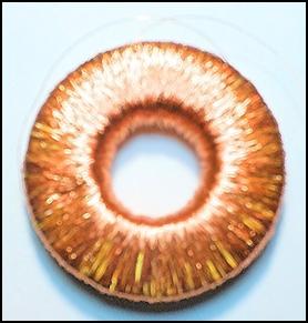 Before we start the experiment, let's determine which surface of the
magnetic ring is the north surface. First, let's check whether the compass is
pointing to the correct side, corner of our room. If so, place the wound
magnetic ring on its edge and bring the compass closer to it. The north side,
which emits gravitational energy, attracts
the black tongue of the compass. Place the magnetic ring on the table so
that its north surface is at the bottom. After mechanically stabilizing the
toroidal coil, let's take care of protecting our health. Let's put on the
protective suit prescribed in the Technical Description of the Antigravity
Drive. Since I didn't have money for one, I took my wool pillow from my bed and placed it on my lap to protect my
internal organs from magnetic radiation. Then I turned on the function
generator, then connected my cheap Deprez instrument to the coil terminals and
set it to alternating voltage.
Before we start the experiment, let's determine which surface of the
magnetic ring is the north surface. First, let's check whether the compass is
pointing to the correct side, corner of our room. If so, place the wound
magnetic ring on its edge and bring the compass closer to it. The north side,
which emits gravitational energy, attracts
the black tongue of the compass. Place the magnetic ring on the table so
that its north surface is at the bottom. After mechanically stabilizing the
toroidal coil, let's take care of protecting our health. Let's put on the
protective suit prescribed in the Technical Description of the Antigravity
Drive. Since I didn't have money for one, I took my wool pillow from my bed and placed it on my lap to protect my
internal organs from magnetic radiation. Then I turned on the function
generator, then connected my cheap Deprez instrument to the coil terminals and
set it to alternating voltage.
First, I scanned the coil with a sine wave. Nothing happened at low frequencies. At 60 kHz, the terminal voltage started to increase. At 830 kHz, it reached 60 V. By increasing the frequency further, the instrument's pointer got stuck. No matter how much I increased the measurement range, it didn't go back. It also got stuck at 1200 V. The same thing happened as with the Tesla coil. The electromagnetic field of the coil induced itself into the instrument's measuring cord. And there was no trace of magnetic radiation. After that, I switched to a square wave. Here, the excitation became more intense. The voltage started to increase at 1 kHz. Now the pointer got stuck at 560 kHz. It didn't go back in the 1200 V measurement range either. Both waveforms were alternating current, i.e. they contained a positive and a negative half-period. I was curious to see how the coil would react to the pulsating DC. I switched the wave to CMOS, i.e. I raised the square wave above the time axis. The voltage increase now started at 25 kHz, and the instrument pointer stopped at 550 kHz.
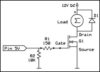 Essentially, all three waveforms behaved the same way, and unlike the
transformers of the Tesla converter, I did not detect a resonant frequency
anywhere. It was clear that the excitation current was low. The max. 250 mA
current output by the function generator is not enough to make the relatively
massive magnetic ring vibrate. Much thicker winding wire must be used for
excitation. Fortunately, I ordered 4 pieces of this magnetic ring, so I did not
have to break the thin wire. I took out the other one. I insulated it with
Mylar tape, then wrapped it around with Ø 0.8 mm thick enameled copper
wire. Its internal resistance became 0.6 Ω. Therefore, this coil can no
longer be connected directly to the 50 Ω output of the signal generator, because it would short circuit.
Essentially, all three waveforms behaved the same way, and unlike the
transformers of the Tesla converter, I did not detect a resonant frequency
anywhere. It was clear that the excitation current was low. The max. 250 mA
current output by the function generator is not enough to make the relatively
massive magnetic ring vibrate. Much thicker winding wire must be used for
excitation. Fortunately, I ordered 4 pieces of this magnetic ring, so I did not
have to break the thin wire. I took out the other one. I insulated it with
Mylar tape, then wrapped it around with Ø 0.8 mm thick enameled copper
wire. Its internal resistance became 0.6 Ω. Therefore, this coil can no
longer be connected directly to the 50 Ω output of the signal generator, because it would short circuit.
Since it is not available ready-made, I made a MOSFET transistor grounded collector circuit. The output resistance of this circuit is between 1 and 10 Ω. Its voltage gain is zero, meaning that the voltage that is output from it is as much as the voltage that is connected to its input. However, its current gain is very high. It is limited only by the power of the power supply and the maximum current of the high-current MOSFET[58] switching transistor. Well, this is exactly what is needed now. First, I tried the simplest version, in which the coil is galvanically connected in series with the MOSFET. I connected the signal generator to its input. First, I tried a sine wave, and then I switched to a square wave. Finally, the CMOS wave, i.e. the pulsating DC voltage, proved to be the most effective.
According to the catalog, the opening voltage of the incremental MOSFET transistors is about. 4 V. I set the frequency of the function generator to 100 Hz and gradually increased the amplitude. At an input voltage of 4.5 V, the transistor opened completely. Since the internal resistance of the MOSFETs is 3-5 mΩ, the value of the current flowing through it is determined by the resistance of the coil. And this was almost 20 A at 12 V. This immediately killed the MOSFET. My intention was to gradually increase the current flowing through the coil, similar to bipolar transistors. That did not work. Therefore, I replaced the transistor and connected a 10 kΩ potentiometer in series with the input. I set the amplitude of the function generator to 5 V and wound the potentiometer. Approx. At 5 kΩ, the MOSFET was still fully open, and it was destroyed by the high current. This is understandable, since a high-power MOSFET is not an amplifier, but a switching transistor. Above the threshold voltage, it is fully open, below it it is completely closed.[59] It is true that it is also used in digital amplifiers, but there it is not controlled linearly, but with pulse-width regulation.
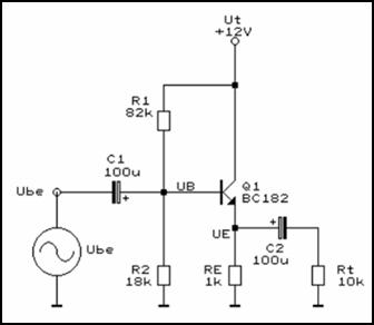 Fortunately, I had another MOSFET. I replaced the damaged transistor,
and then, in order to reduce the current flowing through it, I wound the
remaining Ø 0.8 mm copper wire on the ferrite ring. Its resistance now became 1.2 Ω. This reduced the current
flowing through the transistor to 8 A. This did not destroy the
transistor immediately, but it heated up in a few moments after switching it
on. To prevent its destruction, I quickly disconnected the signal generator
from it. Mounting it on a heat sink would have only extended its lifespan by
seconds. I checked the maximum current of the IRLZ34N
MOSFET. According to the catalog, it's 30 A. Well, that's not enough. Browsing
further, I found 120 A MOSFETs. I quickly ordered from AliExpress.[60]
Since more than 50 planes are already flying between Budapest and major cities
in China every week, the delivery time has been reduced from 2 months to 10
days.
Fortunately, I had another MOSFET. I replaced the damaged transistor,
and then, in order to reduce the current flowing through it, I wound the
remaining Ø 0.8 mm copper wire on the ferrite ring. Its resistance now became 1.2 Ω. This reduced the current
flowing through the transistor to 8 A. This did not destroy the
transistor immediately, but it heated up in a few moments after switching it
on. To prevent its destruction, I quickly disconnected the signal generator
from it. Mounting it on a heat sink would have only extended its lifespan by
seconds. I checked the maximum current of the IRLZ34N
MOSFET. According to the catalog, it's 30 A. Well, that's not enough. Browsing
further, I found 120 A MOSFETs. I quickly ordered from AliExpress.[60]
Since more than 50 planes are already flying between Budapest and major cities
in China every week, the delivery time has been reduced from 2 months to 10
days.
Until then, I tried other circuits. Since I hadn't given up on regulating the current flowing through the coil in some way, I tried decoupling with a capacitor. I thought that by reducing the value of the electrolytic capacitor, the current flowing through the coil would also decrease. The classic bipolar transistor circuit seemed to be the most suitable for this. This is a true grounded collector circuit, since the collector of the transistor is connected directly to the supply voltage. The output signal can be decoupled from its emitter, via a large-capacity electrolytic capacitor. For this reason, this circuit is also called an emitter follower. Since high currents have to be switched here, I replaced the BC182 transistor with a BD245A type, and I reduced the value of the resistors by more than an order of magnitude.
The circuit worked, but very poorly. The biggest problem was that the power transistor heated up strongly even with a collector-emitter current of 1 ampere. This is not surprising, since the maximum current of the BD245A transistor is 10 A. This cannot be increased, because according to the catalogs, bipolar transistors with a current greater than 30 A are not very often produced. And this does not even come close to the maximum current of MOSFET switching transistors of 350 A. What is even worse is that bipolar transistors have a fairly high internal resistance. For this reason, they produce much more heat than MOSFETs. A 30 A bipolar transistor requires a palm-sized heat sink and a large fan.[61] Before I even disassembled the circuit, I replaced the BD245A with a 30 A MOSFET transistor and disconnected the operating point setting resistor divider from the Gate electrode. The current flowing through it jumped to 3 A and did not heat up any more than the bipolar transistor.
Further examination of the circuit revealed that in this case the input electrolytic capacitor is not needed at all. The galvanic coupling controls the MOSFET more efficiently. The output electrolytic capacitor could have reduced the current flowing through the coil as desired, but I was not happy with it. In the emitter-follower grounded collector circuit, the current switched by the transistor does not flow through the coil, but through the emitter resistor. This loss cannot be allowed in the case of a free energy generating device that must feed itself via feedback.
Thus, there is no other option than to adjust the current that the 120-ampere MOSFET can withstand with a heat sink but without fan cooling by reducing the diameter of the coil wire or increasing the number of turns. The question is whether this current will be sufficient to excite the permanent magnet at the resonant frequency. If not, there is still an option to increase the excitation current and avoid heating. Multiple MOSFETs must be used and connected in parallel, similar to a 1000-watt class D amplifier. Industrial designers should consider using Gallium Nitride FETs. GaN FETs are about 20% more efficient than MOSFETs, and the power loss is about a third less. At 2000 W, MOSFETs have a power loss of about 62 W, while GaN FETs have a power loss of only 19 W. This means that the cooling system can be smaller. Also because they are more heat-resistant. They can withstand temperatures of up to 200 °C. Unfortunately, they are not cheap.
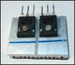 The coil is then put back into the switching circuit. The only
question is whether it should be connected in series with the Drain or Source
electrode? I have already tried connecting in series with the Drain electrode.
In this configuration, the current flowing through the coil is uncontrollable.
Fortunately, the 120-amp MOSFET transistor in the T237 package arrived in the
meantime. I didn't notice much change when I replaced the 30-amp MOSFET in the
T220 package. Despite the larger package and the four times higher maximum
current, it also got hot. The STW150NF55 type MOSFET couldn't withstand the
8-amp current flowing through it for long either. After the 120-amp MOSFET
arrived, I didn't experiment with the 30-amp one any further. Now I connected
the coil in series with its Source electrode. The low internal resistance certainly doesn't cause a problem here, because in
most transistor circuits the emitter and Source electrodes are connected
to ground.
The coil is then put back into the switching circuit. The only
question is whether it should be connected in series with the Drain or Source
electrode? I have already tried connecting in series with the Drain electrode.
In this configuration, the current flowing through the coil is uncontrollable.
Fortunately, the 120-amp MOSFET transistor in the T237 package arrived in the
meantime. I didn't notice much change when I replaced the 30-amp MOSFET in the
T220 package. Despite the larger package and the four times higher maximum
current, it also got hot. The STW150NF55 type MOSFET couldn't withstand the
8-amp current flowing through it for long either. After the 120-amp MOSFET
arrived, I didn't experiment with the 30-amp one any further. Now I connected
the coil in series with its Source electrode. The low internal resistance certainly doesn't cause a problem here, because in
most transistor circuits the emitter and Source electrodes are connected
to ground.
However, the MOSFET did not react as expected to this mode. The main change was that its opening voltage was not 4-5 V, but 10 V. Even there, it only opened halfway. In order to open it completely, the amplitude of the function generator had to be increased to 20 V. In addition, it got very hot. This was probably because it was at the beginning of opening. The control voltage must be set in such a way as to bring the transistor out of the curvature section of its output characteristic. In the initial stage, the internal resistance of the MOSFET is still high, as a result of which it has to dissipate more heat. (Tesla didn't have such problems. He used a commutator as a pulse generator, which he drove with a smaller motor. As we know, there is an insulating material between the cylindrical commutator strips. This means that the carbon brush, when in contact with the commutator strips, created zero resistance, while the insulating material created infinite resistance. Thus, there was no dissipation.)
The emitter follower, and now the source follower circuit, did not work here. Therefore, I put the coil back in the Drain circuit. Here, the STW150NF55 type MOSFET was working properly, but I was not satisfied with its heat tolerance. Despite the larger case and the four times higher maximum current, it also got hot. It also could not withstand the 8 ampere current flowing through it for long. But it did not break down, it did not short-circuit. I put it on a smaller heat sink. (It is recommended to coat the back of the transistors with thermally conductive silicone paste beforehand.) This helped a lot. The heat sink could withstand the high current flowing through it for half a minute. After AliExpress shipped 10 of these transistors, I added another one next to them[62] and connected the two in parallel.
Since field-effect transistors have a very high input resistance, I could not control the degree of opening with a resistor connected in series with the Gate electrode. However, I could control the magnitude of the input voltage. By increasing the amplitude of the signal generator, the MOSFET gradually opened. This way I was able to bring it out of the curved section of its output characteristic. At a supply voltage of 12 V, when the MOSFET is fully opened, a maximum of 8 A flows through the coil. The question is whether it can handle this without heating up.
Those with decades of professional experience still remember the sizing of traditional SiFe iron-core transformers. Transformers are no longer made from this EI-shaped laminated iron core, although its maximum flux density is five times that of a ferrite core. The reason for this is that it saturates at 150 Hz. It cannot be used at high frequencies. The maximum induction of a traditional SiFe iron core is 1.2 T, that of a wound hypersil iron core is 1.6 T, and that of a ferrite iron core is only 0.3 T. For this reason, it can be excited up to several hundred kHz. As a superficial observer, I might wonder what can be done with a transformer that is only one fifth as powerful, even if it is high-frequency. This is where the previously mentioned miraculous effect, which can be attributed to the ether, comes into play. At high frequencies, ether particles often collide with atoms and shake more electrons from their outer electron shells than the excitation voltage can separate. Recognizing this, toroidal ferrite iron cores are used in almost all power supplies today. (Power supplies made for audiophiles are still linear because they are absolutely silent. They do not produce EMI or EMF radiation, they do not introduce any noise into the program you are listening to. However, they are large, heavy and very expensive.)
This etheric effect occurring in the primary winding is also transferred to the secondary winding, which is why higher currents flow here too. When designing traditional laminated transformers, a maximum current of 2.5 A per square millimeter had to be calculated. This current did not overheat the transformer, and no short circuit occurred. The question is, what is the situation here? In this case, the magnitude of the excitation current depends on the frequency at which the resonance occurs. Let's stay at 2.5 A for now. In this case, we will not even approach the 8 amperes measured in the previous tests. The cross-section of the Ø 0.8 mm enameled copper wire is rounded to 0.5 square millimeters, which allows 1.2 amperes. (D = 12 × π/4. Further simplified: I2 × 0.75, or 0.8 × 0.8 × 0.75 = 0.48 mm2. 0.48 × 2.5 = 1.2 A) At this current, the MOSFET will not even sweat. The question is whether this much current will be enough to trigger resonance. If not, there is still a reserve in the excitation circuit.
Unfortunately, after half a minute, the two MOSFETs mounted on the heat sink also started to get very hot. I looked around to see if there was a MOSFET with a higher current. I found a 350 ampere one. I ordered it from AliExpress right away. (It was only slightly more expensive than the 120 ampere one. These high-current switching transistors are fantastically cheap. They are even cheaper than high-power bipolar transistors, as they are easier to manufacture.) In the meantime, I investigated further. After the 250 mA electromagnet proved to be too weak, and the version wound with Ø 0.8 mm wire shorted the power supply, I took out the third magnetic ring and wound it with Ø 0.45 millimeter copper wire. I put enough turns on it so that its resistance was 2 Ω. This way, with a 12 V supply voltage, a maximum of 6 A could flow through it. My power supply could handle this, and for a while the MOSFETs too. In order to get the initial curved section of the output characteristic out, I set the control voltage to 10 V.
I started the scan again at 100 Hz. Here everything worked perfectly. The oscilloscope showed regular square signals with an amplitude of almost 12 V on the coil. Moving up, self-induction spikes with an amplitude of 80 V at 1 kHz appeared on the square signal. I shunted these negative spikes with the opposite sign with the reverse-bias diode D1, which is also visible in the circuit diagram. Not for long. The low-power Schottky diode started to smoke after a few seconds and failed. I put a 200-ampere diode on top of it. It also got very hot, but did not fail. That is why I removed it from the circuit. The self-induction voltage, which was well above the supply voltage, did not destroy the MOSFETs with a reverse voltage of 75 V. The current flowing through the coil was only max. 3 A, since the duty cycle of the signal generator is set to 50% by default. In other words, current flowed only half of the period, and there was a pause signal during the other half. Despite this, the coil became very hot, which is no wonder, since the cross-section of the copper wire was now only 0.3 mm2. For this reason, the experiment often had to be interrupted to cool down. However, the MOSFETs did not heat up. They could withstand the max. 3 amperes without heating up.
By further increasing the frequency, the current flowing through the coil gradually decreased. At 110 kHz, it dropped to 200 mA.[63] At 180 kHz, however, it rose to over 3 A. Resonance occurred. The coil resonated, but the magnet did nothing. Not a single spark of monopole came out of it. The electromagnet could not bring the magnetic ring into resonance. By further increasing the frequency, the amplitude of the signal measured on the coil gradually decreased. The magnetic ring saturated, it could not follow the increased frequency. However, the current did not decrease, because the square wave signal was converted into a DC voltage, which caused not only the coil, but also two MOSFETs to start heating up.
I was curious whether this saturation was current-dependent. I inserted the magnetic ring wound with Ø 0.2 mm copper wire. In this circuit, it behaved completely differently than when driven directly by the function generator. Here too, resonance occurred at 180 kHz, and saturation also occurred at the same frequency. It became clear that these frequency values do not depend on the magnitude of the excitation current or excitation voltage, but on the quality of the iron core, in this case the ferrite ring. The magnitude of the excitation current only affects the amplitude of the self-induction spikes. The cut-off frequency of this MnZnFe ferrite ring is 200 kHz.
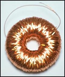 In order to reduce the heating of
the coil, I wound so many more turns on the magnetic ring wound with
0.8 mm enameled copper wire that its resistance would also be 2 Ω. Since
the 350 ampere MOSFET had arrived in the
meantime, I replaced the 120 ampere ones with these. Unfortunately,
the renewed circuit behaved the same as the previous ones. Its resonant
frequency and saturation frequency were the same. Only the coil and the
IRFP4368 type MOSFETs heated up less. It is
incomprehensible why a transistor with a peak current of 350 A mounted
on a heat sink heats up when only 6 amps are flowing through it? A common
feature of all three coils is that when operated at resonant frequency, their
EMI radiation increased greatly, which interfered intensely with the radio.
In order to reduce the heating of
the coil, I wound so many more turns on the magnetic ring wound with
0.8 mm enameled copper wire that its resistance would also be 2 Ω. Since
the 350 ampere MOSFET had arrived in the
meantime, I replaced the 120 ampere ones with these. Unfortunately,
the renewed circuit behaved the same as the previous ones. Its resonant
frequency and saturation frequency were the same. Only the coil and the
IRFP4368 type MOSFETs heated up less. It is
incomprehensible why a transistor with a peak current of 350 A mounted
on a heat sink heats up when only 6 amps are flowing through it? A common
feature of all three coils is that when operated at resonant frequency, their
EMI radiation increased greatly, which interfered intensely with the radio.
The biggest problem is not this, but the lack of particle radiation. I struggled with it for days. After several attempts, it turned out that this method could not produce free energy, or as many call it, free energy. No matter how I changed the circuit, more current went in than came out of it. It became clear that electrons are unable to excite the domains, to set them in motion. This is understandable, because the domains have 70 times more power than free electrons. The power of the domains is surpassed only by their energy content. Richard Feynman calculated the equivalent mass of the ether per unit volume. The famous physicist got 2 billion tons/cm3 as a result. Converted using Einstein's well-known formula, this mass would provide enough energy to boil the world's oceans. And all this energy is contained in a single cubic centimeter of the universe. There is no need to fear that this energy will run out one day. The universe is almost infinite, so even if we lived forever, we wouldn't be able to use up that much energy. Unfortunately, we don't have access to this sea of energy yet, at least not in this way. This idea of mine also failed. This is my third fiasco in resonant frequency excitation
Budapest, October 23, 2024.
![]()
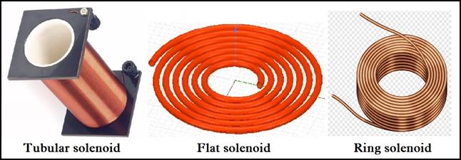 Despite my series of failures, I continued my research. Roaming
the Internet, I stumbled upon the copper wire version of reverse magnetic
excitation. Reverse magnetic excitation is commonly used by extraterrestrial
civilizations in their anti-gravity engines. The most common design method is
the mercury circulation gear. Magnetic monopoles can also be excited by reverse
magnetic excitation of electromagnets, but
for this they must be rotated. The "little grays" from the Zéta Reticuli
star system gave us a demonstration with a minor modification of an electric motor.
Then they turned on the power and the motor started to fly back and forth. He
ended up hitting the ceiling before the power cord broke off and he fell. (Only
the poles of two opposite coils were changed.)
Despite my series of failures, I continued my research. Roaming
the Internet, I stumbled upon the copper wire version of reverse magnetic
excitation. Reverse magnetic excitation is commonly used by extraterrestrial
civilizations in their anti-gravity engines. The most common design method is
the mercury circulation gear. Magnetic monopoles can also be excited by reverse
magnetic excitation of electromagnets, but
for this they must be rotated. The "little grays" from the Zéta Reticuli
star system gave us a demonstration with a minor modification of an electric motor.
Then they turned on the power and the motor started to fly back and forth. He
ended up hitting the ceiling before the power cord broke off and he fell. (Only
the poles of two opposite coils were changed.)
 The method of excitation with insulated copper wire is not a
new concept. Tesla's 1893 patent #512,340 includes an electromagnetic coil that
is wound around a tube, where the two spirals are back to back. The special
feature of the design is that the end of one coil is connected to the beginning
of the other, that is, they are not connected in series, but in the opposite
direction. So Tesla already invented reverse magnetic excitation 120 years ago.
In his patent description, Tesla notes that this specially arranged double coil
can store many times more energy than a conventional single coil.
The method of excitation with insulated copper wire is not a
new concept. Tesla's 1893 patent #512,340 includes an electromagnetic coil that
is wound around a tube, where the two spirals are back to back. The special
feature of the design is that the end of one coil is connected to the beginning
of the other, that is, they are not connected in series, but in the opposite
direction. So Tesla already invented reverse magnetic excitation 120 years ago.
In his patent description, Tesla notes that this specially arranged double coil
can store many times more energy than a conventional single coil.
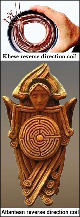 However, the electrical industry uses reverse magnetic excitation only
to make self-induction-free resistors, in the form of bifilar winding. A
bifilar coil is a coil made by winding two wires in parallel, in which the
current flows in opposite directions. Since the winding direction of the two parallel
fibers is the same, but the direction of the current flowing in them is
opposite, their magnetic fields will be in opposite directions. Because of this, they
mutually reduce each other's effect. Thus, the resulting inductance is
negligible.
However, the electrical industry uses reverse magnetic excitation only
to make self-induction-free resistors, in the form of bifilar winding. A
bifilar coil is a coil made by winding two wires in parallel, in which the
current flows in opposite directions. Since the winding direction of the two parallel
fibers is the same, but the direction of the current flowing in them is
opposite, their magnetic fields will be in opposite directions. Because of this, they
mutually reduce each other's effect. Thus, the resulting inductance is
negligible.
However, according to esoteric literature, this method of stimulation is capable of much more. It is not possible to excite electromotive force in a counter-connected winding (consisting of a parallel conductor bent in half), because the induction in the two conductors works against each other. Electromagnetic flux is therefore not created, but opposite excitation is realized, as a result of which a significant amount of Yin and Yang subatomic energy is generated. In a bifilar coil, only the electromotive force lines cancel each other, the magnetic force lines do not. These add up and have a stronger effect. This energy is much more than what is added up from turn to turn in a normal electromagnet. Its power even exceeds the level of magnetic energy produced by self-induction.
Here, the excess energy is not only provided by the high-frequency excitation of the copper atoms, but also by the opposite excitation. This is also the work of the ether. In this arrangement, the free electrons flowing in the opposite direction help to separate the free electrons of the ethers. Thus etherons now have to do double work. Because of the high noise, there is less space available in the copper conductor, so more copper atoms collide. This causes even more electrons to be removed from their outer electron shell. The force of inertia also increases the disturbance in the coil, because the free electrons flowing in a spiral orbit are constantly bumping into the ether wall that weaves through all matter. The large number of free electrons and the copper atoms pushed together end up displacing some of the etherons and gravitons from the coil. This is due to the Yin and Yang type of particle radiation, which is not nearly as large as if the domains pushed them out of the permanent magnet. However, this energy cannot be used in a conventional way. It is not possible to make an electric motor or generator from an electromagnet wound in this way, because here the split electromagnetic waves (gravitational and etheric radiation) flow out from the poles.
Well then, let's see the exercise. It didn't take long to
prove the theory. I thought I would increase the efficiency, so I started
experimenting with iron-core and permanent magnet electromagnets. I did not
supply these with bifilar winding, but placed the two windings on top of each
other and connected them in series in the opposite direction. Nothing happened.
Driven by MOSFET tran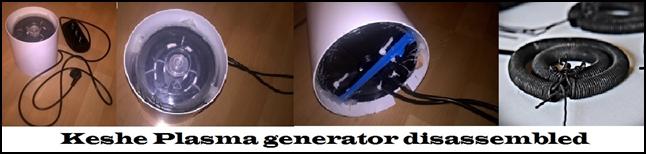 sistors, they acted as electromagnets. They did not want to act as a
magnetic monopole. With an iron-core coil, I couldn't extract electricity from
the Tesla coil either. When I hung a small transformer in it, its iron core
saturated and got hot. It did not act as an electromagnet. It is no coincidence
that Tesla and his successors exclusively used air-core coils for this
purpose. There are four versions of this: The ring-shaped, the cylindrical,
the flat and the one tied in the opposite direction. I tried all four. It
turned out that the excitation power I used is not enough to excite air-core solenoids. The 6 A current that the
transistors could withstand without heating up took about 70
sistors, they acted as electromagnets. They did not want to act as a
magnetic monopole. With an iron-core coil, I couldn't extract electricity from
the Tesla coil either. When I hung a small transformer in it, its iron core
saturated and got hot. It did not act as an electromagnet. It is no coincidence
that Tesla and his successors exclusively used air-core coils for this
purpose. There are four versions of this: The ring-shaped, the cylindrical,
the flat and the one tied in the opposite direction. I tried all four. It
turned out that the excitation power I used is not enough to excite air-core solenoids. The 6 A current that the
transistors could withstand without heating up took about 70 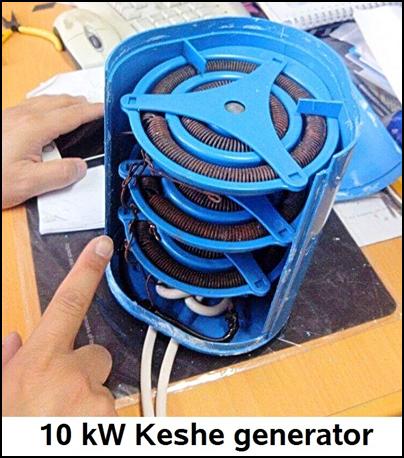 W from the 12 V power supply. And this is not enough for air-core
coils.
W from the 12 V power supply. And this is not enough for air-core
coils.
For this, Dr. Keshe also found out, who in the meantime developed a resonant frequency generator.[64] He also got the idea from Tesla. He probably also started with low voltage, but soon realized that this excitation required kilowatts. But where to get more kW of excitation power. Since the magnetic current is small in this case, even now more current will enter than come out. That's when he came up with an idea, let's use the mains current for excitation. An average household has a 16-amp circuit breaker, which means that approx. 4 kW output can be selected. This is more than enough to excite you. And he protected the loss due to the low excitation current by applying the excess current to the mains current. In other words, the excitation took place in the network line.
However, the excess current was still small. Therefore, he did not place the two scrolls on top of each other, but made a smaller and a larger scroll, and placed the smaller one inside the larger one. This helped a lot, but it was still not enough. Therefore, he wound both coils into a spiral. Then he placed two coils similar to spiral springs inside each other and then connected them in the opposite direction. Thus, you have already achieved a 70% energy surplus. (It provides 2-3 kW of energy in the size of a 3-liter mason jar. It is also produced in larger sizes. The maximum output is 10 kW.)
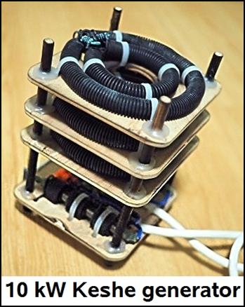 This performance could probably be further increased if the solenoids
were excited at the resonance frequency.
However, this is impossible, because there is no transistor capable of
switching 40 kW. Even Tesla's commutator chopper wouldn't be able to do
that. The strong current would cause a fire in the commutator, which would heat
up the metal chips and the carbon brush and burn the insulation between them.
So Keshe had to make do with 100 Hz alternating mains current. Since the power
of batteries in electric cars is at least 40 kW, there was no obstacle to
installing the device in cars as well. Its power was not enough to power the
car on its own, but it significantly increased the range of the electric
vehicle.
This performance could probably be further increased if the solenoids
were excited at the resonance frequency.
However, this is impossible, because there is no transistor capable of
switching 40 kW. Even Tesla's commutator chopper wouldn't be able to do
that. The strong current would cause a fire in the commutator, which would heat
up the metal chips and the carbon brush and burn the insulation between them.
So Keshe had to make do with 100 Hz alternating mains current. Since the power
of batteries in electric cars is at least 40 kW, there was no obstacle to
installing the device in cars as well. Its power was not enough to power the
car on its own, but it significantly increased the range of the electric
vehicle.
However, the sale caused complications. Since the Keshe Foundation did not receive support from anyone, and the employees had to be paid, Dr. Keshe tried to solve this problem by trying to sell his product at an unrealistic price. He sold his product consisting of two spiral springs and a capacitor for 800 euros. (This is HUF 320,000 at the current exchange rate.) Therefore, it did not sell well for that price. Therefore, your business probably went bankrupt. His website is also gone. He might as well have been purged from the Internet like Hamel's anti-gravity engine. There is a suspicion that he himself completely finished his activities criticized by many. He was forced to take this step due to a lack of support. Politics also influenced his work. President Obama banned Western countries from mass marketing this product. This would have greatly jeopardized the export of crude oil and liquefied natural gas produced in America.
What happened to Dr Keshe should be investigated. Is he still alive at all? If so, it would be great if you could reveal what actually happened to this invention. Those interested in the details of the case should watch Dr. György Egely's video on the Internet.[65] By the way, this device was glorified 12 years ago. There is also a video about this on the Internet.[66] And a report made 10 years ago reported that Dr Keshe distributed free devices to many ambassadors, mainly from Africa and the Middle East, at an international meeting he convened. (Ambassadors of Western countries did not dare to accept the invitation.) At the same time, he announced that the patents will expire on October 26, 2015, and will not be extended or appropriated. This makes it freely available to anyone. The Keshe Foundation's Free Energy Conference was broadcast live from Rome on several satellites and 3 internet channels.[67]
Unfortunately, this device is no longer available. Clicking on http://keshefoundation.org/webshop/products displays a 404 Page Not Found message. In order to dispel doubts, you should find someone who, 12 years ago, was still able to buy a Keshe generator that can be used in a household or in a car. He could report on his experiences. Disassembling and measuring the device would make it clear whether your invention is a usable product or a fraud. If fraud has occurred, this development is the fourth fiasco in the history of resonant frequency excitation.
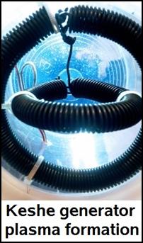 If this generator is functional, we will not go far with it either,
because it is not an independent producer of free energy. It is connected to
the mains electricity, so it cannot be disconnected from the electricity
network. There is still a need for power plants, high-voltage transmission
lines and electricity providers. In this way, it does not help clean the air,
stop or reverse global warming.
If this generator is functional, we will not go far with it either,
because it is not an independent producer of free energy. It is connected to
the mains electricity, so it cannot be disconnected from the electricity
network. There is still a need for power plants, high-voltage transmission
lines and electricity providers. In this way, it does not help clean the air,
stop or reverse global warming.
At the end of my research, I found a photo of the plasma allegedly produced in the Keshe generator. This photo is either a real photo or a photo montage. If it's real, I don't see why Keshe didn't take advantage of this physical phenomenon. Free energy must not be produced with the generator, but with the solenoid placed above, below or around it. Magnetic monopoles can generate seventy times more electricity than electromagnetic excitation. If you had implanted a toroidal or flat solenoid in the plasma, you might have been able to extract more electricity than you could with the reverse coil doing the excitation. You don't need an inverter for this free energy either, because the 50 Hz alternating current is provided. In the case of the ring-shaped solenoid, enough turns must be wound so that the output voltage is 230 V. The current can be increased with the wire thickness.
The plasma formation is due to the intense jostling, causing the etheric particles to compress and emerge from the coil as a concentrated wave. The concentration is so strong that the energy wave ionizes the air around the generator, which manifests as plasma similar to a corona discharge. We can also deduce the intensity of the energy concentration from the color of the plasma. At the lowest level, it is red, then as it intensifies, it follows the colors of the rainbow. It becomes orange, yellow, green, blue, and finally violet. It is so intense that we see it as blinding white. This strong white plasma also surrounds UFOs cruising in the sky. The production of this strong radiation poses many dangers to our health and safety. We can protect ourselves against this with the protective clothing described in the study Antigravity Drives. Anyone who does not take this seriously risks his life.
Small amounts of radiation do not cause cancer, but they upset the balance of our meridian system. Unlike electromagnetic lines of force, in particle radiation, the same poles do not repel, but attract each other. Therefore, intense etheric radiation mainly extracts energy from our Yang meridians. This is mostly manifested in headaches, nausea, malaise, insomnia, depression, and impaired vision. It is in vain that we go to the doctor with this disease, but he cannot do anything about it. The diagnostic tools currently used by medicine do not reveal the real cause of the symptoms. However, we can replace the extracted energy with magnetopressure. Use the Yin (black) end of the magnetic rod to inject energy into the tonic points. The method of application of this procedure can be found in the volume Esoteric Panorama. (Other esoteric works also contain a few sections describing this healing procedure, which is even more effective and cheaper than acupuncture.)
Budapest, December 24, 2024.
![]()
Unfortunately, I did not receive any help with this development either. No one is willing to cooperate with me. I was unable to obtain a Keshe generator, so I could not determine what was wrong with this device. That is why I suspended this development. I am not too keen on reconstructing this generator because it does not allow disconnection from the mains. With its use, power plants, transmission lines, and energy providers[68] who blackmail consumers will continue to exist. A free electricity generator independent of the network is needed. Something like the Tesla converter, the reconstruction of which I was also forced to suspend due to lack of cooperation.
In the search for new ways, I tried to extract energy from permanent magnets, which did not work. Electrical excitation proved to be weak for this. It is increasingly likely that the domains that condense and displace etheric energy can only be made to work by mechanical movement. This was clearly proven during the study of the operating mechanism of the Hamel generator. There was a successful experiment in this area. The American Chris Felton extracted a huge amount of energy from this generator with just a wire loop. The problem with the Hamel generator, however, is that it is difficult to manufacture. In order for it to work properly, the aluminum cones cannot be produced by riveting. In order to wobble symmetrically in all directions, a deep-drawing tool is needed, which only a well-equipped machine shop has. The design of the steel barrel and the stable placement of the permanent magnet plates are not easy either. The wear of the granite balls and the two textile bakelite plates will also cause problems. These must be replaced every few years. There is no such problem with compact generators containing moving parts.
But how can this be done? What could bring the ferrite ring into resonance without moving parts? Tesla invented this too. He made a device the size of a palm, with which he almost brought down a tower block. He attached his infrasound generator to one of the beams of a half-finished ten-story building. He tuned it to the resonant frequency of the building. The tower block creaked and creaked. Seeing this, the workers fled in panic, thinking it was an earthquake. They also called the police. At that moment, Tesla put his device in his pocket and walked away from the scene. As he later noted, he could have demolished the building in 10 minutes.[69]
What was in this little device? It was certainly not a mechanical device that rhythmically knocked on the beam, because it would not have fit inside. Only the loudspeaker and the Hall element are capable of producing sounds of different frequencies. The sound scattered by the loudspeaker cannot be concentrated, but the sound emitted by the piezo disc can. It just needs to be tightly fitted to the object to be vibrated. The Hall element, which causes the piezoelectric effect, is an old invention. The Hall effect was invented by a German physicist, Edwin Hall, in 1879. This already existed in Tesla's time.
If Tesla used a piezoelectric disc, then this proves that the sound waves emanating from it are able to cause magnetic domains to vibrate. Let's try to see if it can really produce this effect. Back in November 2024, I ordered 20 mm diameter piezo discs from the AliExpress web store. They were fantastically cheap. They sent 20 pieces for 1660 forints. I picked them up. At first, I experimented with just one piece. I connected it to the function generator and excited it with a square wave. (Now it didn't matter whether I used a full wave with a negative half-period or a square wave raised above the time axis.) The disc vibrated, but only hummed softly. As the operating voltage (amplitude) increased, its volume increased proportionally. According to the brochure, its cut-off frequency is 1.5 kHz, but it still vibrated at 5 kHz. In fact, it was the loudest there.
Since it is a capacitive load, the piezo discs consumed very little current. At an amplitude of 10 V, vibrating at 4 kHz, 1 disc consumed only 1.7 mA of current. Then I started connecting them in series. Gradually, the volume and current consumption decreased. 4 discs consumed only 0.7 mA of current. (It didn't matter how I connected the red and black wires to each other. They worked the same with reversed polarity.) Obviously, you can't increase the excitation in this way. Then I started connecting them in parallel. Their current consumption increased. 2 discs consumed 2.9 mA, 3 discs 4 mA, and 4 discs 7 mA of alternating current. Their volume also became slightly louder, although it still sounded like the chirping of crickets.
However, I was not sure that audible sound waves were needed for excitation. I had previously developed a complete fire and burglary protection product line, which also included a glass break sensor. In this, I glued the piezo disc to a thin ceramic chip. I then glued this chip, together with the signal detection circuit, to the glass surface to be protected. Here, the signal generated by the vibration flowed back, but the air gap would have rendered the device inoperable. The problem here could be that the vibration is not intense enough and cannot penetrate the magnetic ring. I found several circuit diagrams on the Internet where the piezo disc is vibrated by power transistors. The signal generator is used to control the transistors.
For this purpose, I first used the MOSFET transistor circuit used to excite coiled electromagnets. I connected the piezo discs in place of the removed electromagnet. Nothing happened. This is understandable, since the piezo-disk is a capacitive load, so no current flows through it. Therefore, I put a 100 Ω resistor in place of the electromagnet, and soldered the piezo-disks connected in parallel to its legs. The result was disappointing. They did not sound any louder than when excited directly with the function generator. The output load of the function generator is 250 mA, and this value was not consumed by the 4 piezo-disks together. Therefore, there is no need for current amplification here. The problem is not with this, but with the size and thickness of the piezo-disks. These low-mass disks are not able to produce significant sound pressure. They are cheap, but they are not worth much. They would not even be good for computers, they would be beeping.
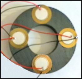 After that, I glued the 4 disks onto
the surface of a 70 mm diameter ferrite magnetic ring Yang. I suspected
that this low sound pressure would not be able to make the toroidal magnet
vibrate. The result was even worse. The discs stopped vibrating completely, and
the current they drew dropped to 7 mA. The
metal mass, which was orders of magnitude greater than that of the piezo
discs, paralyzed them, and they could not
vibrate. It is clear that for this purpose piezo discs that produce
vibrations at least an order of magnitude more intense are needed. But what
kind of discs? Those that produce a strong sound, or those that, when glued to them, can make the magnetic ring vibrate.
What excites the toroidal magnet? Sound waves or mechanical vibration? If sound
waves, then this will make a very noisy generator. It is unbearable in the
apartment. You have to take it out into the
yard, hide it in a deep, formworked hole, and put thick paving slabs on
it so that you cannot hear its operation.
After that, I glued the 4 disks onto
the surface of a 70 mm diameter ferrite magnetic ring Yang. I suspected
that this low sound pressure would not be able to make the toroidal magnet
vibrate. The result was even worse. The discs stopped vibrating completely, and
the current they drew dropped to 7 mA. The
metal mass, which was orders of magnitude greater than that of the piezo
discs, paralyzed them, and they could not
vibrate. It is clear that for this purpose piezo discs that produce
vibrations at least an order of magnitude more intense are needed. But what
kind of discs? Those that produce a strong sound, or those that, when glued to them, can make the magnetic ring vibrate.
What excites the toroidal magnet? Sound waves or mechanical vibration? If sound
waves, then this will make a very noisy generator. It is unbearable in the
apartment. You have to take it out into the
yard, hide it in a deep, formworked hole, and put thick paving slabs on
it so that you cannot hear its operation.
To solve the dilemma, you need to try both vibration modes. I looked around the AliExpress web store again to see what they offer for this purpose. After a long search, it turned out that buzzers are the best for making noise. Among them are alarms. There was one that produced a sound pressure of 110 decibels. This can even damage your eardrums. From the list in the appendix, I ordered 2 each of the BJ 1K DC 12 V, the 110 dB Car Start Voice, and 4 of the extremely cheap High Decibel Active Buzzer Alarm Speaker. For the adhesive mode, I ordered 4 of the Diameter 50mm 40K 35W Ultrasonic Transducer discs. This wasn't expensive either. Some web shops charged four times as much for the same thing.
After ordering them, I realized why they are so cheap. They are shipped by cargo ship, which spends weeks bouncing across two oceans before they reach Europe. For this reason, they gave a delivery deadline of April. (Luckily, they arrived earlier.) Since these 50-60 mm diameter discs do not fit on my 70 mm outer diameter ferrite ring, I ordered 1 pc of 100 mm, 120 mm and 156 mm outer diameter ferrite magnets from the American TEMU webshop. (The exact type of these can also be found in the enclosed compressed folder.) Since TEMU ships by plane, these arrived here in a week, but I did not go far with them, because I have nothing to excite them with yet.
When the high-performance discs arrive, excitation with ether noise must also be investigated. In electromagnetic development, excitation with ether noise was the least effective. Here, however, it was a big surprise that when using the Noise waveform, the piezo discs' consumption of a few milliamperes jumped to 210 mA. I was very happy about this, because I thought that the efficiency of the piezo discs had increased by orders of magnitude. I soon realized that this was not the case, because their volume had decreased so much that I could barely hear their humming. When measured with an oscilloscope, the 10 V amplitude (supply voltage) had decreased to 3 V. The piezo discs glued to the toroidal magnet behaved in the same way. Their current consumption was max. 7 mA for all waveforms. But what is this excess current? Capacitive current? The investigation is complicated by the fact that this consumption spike does not occur with the piezo discs glued to the magnetic ring. They are also paralyzed when excited by a noise wave.
Budapest, February 06, 2025.
![]()
Since the piezo discs will arrive in two months, I thought I would try to clarify what the situation is with Keshe's free energy generating device. I watched the videos about it again, and I have a growing suspicion that Keshe was unable to make this device work because he did not understand its operating mechanism. And if someone does not understand how his invention works, is not aware of the physical law that makes it work, then it will never become a usable tool or device. Dr. Keshe published a thick book about the operating principle of his invention, which is full of vague physical explanations. His critics criticized these confusing views, and many even made them the subject of ridicule. I wonder what is true in this.
Dr. Keshe's work is full of statements that the operating principle of his device is based on the operating principle of bio-fusion reactors in plants. He continues his discussions with strange force fields. There are many amoeba-like diagrams in his book that are incomprehensible. What can be done with this principle? Scientists are getting a brain hemorrhage from these statements. The execution is even more mysterious. He made the spirals not from enameled, but from bare copper wire, which he coated with sulfate and other coatings consisting of various chemicals. Creating these coatings, similar to electroplating, required great attention and several days. Then the device had to be shaped for weeks so that the coatings thickened. Keshe claimed that energy spreads in this thin “Nano Coating”. The excess current is created by the coating not allowing magnetic energy to escape from the coil, and thus the generation of electricity becomes more efficient. A few pages later, he claims that this coating attracts energy from the ether into the coil.
Well, then let's pour clean water into the glass. In Keshe's device, the coils were made of copper wire with a diameter of 2.5 mm. I only had 1.6 mm enameled copper wire. It has a lower power, but it should still work. I took the thickest wooden spoon from the kitchen cupboard and wound all the wires around its handle.[70] I bent the smaller coil into a circle and placed it inside the larger one. Then I soldered the ends of the coils together in the opposite direction and soldered the input and output power cords. Then I plugged it into the outlet. It didn't explode, it didn't catch fire, and it didn't trip the circuit breaker. That's half the battle.
Well, let's load this one too. I only have an 800 W heater, but it's good for testing. First, I measured how much current it draws from the network. This can be easily calculated from the well-known P=U×I formula. 800=230×I. I=800/230. This is rounded to 3.5 A. That's what the meter measured. I connected it to the output of the Keshe generator. It heated up in the same amount of time, and its heating element shone just as brightly as if it were connected directly to the mains. Now the monkey jumps into the water. (This is a Hungarian proverb.) I connected the ammeter between the generator and the heat radiator. It showed the same amount as before, that is, 3.5 A. There is no point in embellishing the matter, this generator does not work. And there is no sign of plasma formation.
However, many people used the generator made by Keshe, and they swore that it worked for a while. But why? It is also strange that in the photographs taken of the Keshe generator, the ends of the spiral coils are not soldered together, Keshe just twisted them together. As if it was not the copper that conducted the current, but the coating on it. If this is true, then a phenomenon similar to the skin effect occurs here, only in this case, not electrons, but subatomic energy particles transmit the energy. Since water conducts electricity, this solution can work, but only for a while. Until the coating dries out. Well, after that, the Keshe generator stopped working. That's when the complaints came from the customers. Because of this, Keshe recalled the generators, smeared them with the magic coolness again, and sent them back. They worked again for a while, and then the whole circus started all over again.
In order to prevent this, he came up with a "30-day conditioning period" for the device. This is a tricky requirement because online stores only have two weeks to return a device that doesn't work or that we don't like. This way, the manufacturer can easily fend off complaints that the customer ran out of time. This then became such a scandal that Keshe stopped manufacturing his device and deleted his website from the Internet. Then he disappeared from the public eye. If the coating really did conduct electricity, then it would be worth determining its composition using a spectrometer. Maybe there is some chemical or mineral in it that conducts magnetic current. If such a substance is found in it, a lot can be done with that.
According to Keshe, this coating serves the purpose of preventing energy from escaping from the copper wire. This statement is also lame. If magnetic waves do not escape from the wire, then how does the counter-magnetic excitation occur? Since the excitation of the coils here does not occur at a resonant frequency, the only possibility for the production of free energy is counter-magnetic excitation. It is more likely that this coating reduced the resonant frequency of the coils. This brought it closer to the mains frequency of 50 Hz. Thus, the excitation became more efficient. However, as the coating dried out, this effect disappeared. The resonant frequency of the coils increased again, which is why the generator stopped.
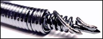 For verification, I also built the Keshe generator from enameled
copper wire with a diameter of 0.7 mm. To avoid overload, I connected 3 100 W
incandescent lamps to its output. That didn't work either. Then I put on my
thick electrician's rubber gloves and tried the method used by the Polish
developers. I placed the thicker outer spiral
on top of it and then the inner spiral. Nothing happened this time
either. The plasma in the photo is probably a photomontage. Finally, I tried a
strange solution I found on the Internet. In this version, the two spiral coils
are not placed next to each other in a circle, but are built into each other.
They make a spiral with a larger and a smaller diameter, and the smaller
diameter is inserted into the larger one. This experiment didn't work either.
For verification, I also built the Keshe generator from enameled
copper wire with a diameter of 0.7 mm. To avoid overload, I connected 3 100 W
incandescent lamps to its output. That didn't work either. Then I put on my
thick electrician's rubber gloves and tried the method used by the Polish
developers. I placed the thicker outer spiral
on top of it and then the inner spiral. Nothing happened this time
either. The plasma in the photo is probably a photomontage. Finally, I tried a
strange solution I found on the Internet. In this version, the two spiral coils
are not placed next to each other in a circle, but are built into each other.
They make a spiral with a larger and a smaller diameter, and the smaller
diameter is inserted into the larger one. This experiment didn't work either.
In the meantime, ferrite rings of different diameters and mini horns arrived one after another. I had high hopes for trying them out. However, my enthusiasm quickly subsided. First, I tried the version without electronics with an outer diameter of 52 mm and a height of 30 mm. Its volume was 125 dB, which can cause hearing damage. Since it did not contain a square wave generator, I connected it to my signal generator. It made a deafening noise. It was so loud that I could only bear it with earplugs. Its volume was strongest at 3.5 kHz, and at frequencies higher than 7 kHz it no longer emitted an audible sound. I took out the 70 mm diameter ferrite magnet ring and put the mini horn on it. Nothing happened.
I started moving the horn. This did not trigger the hoped-for plasma radiation either. I placed the compass next to it, but it did not detect an increase in the radiation from the magnet ring either. I performed this test with the 100 and then the 120 mm diameter ferrite magnets. These did not react to the strong sound wave either. With all three ferrite rings, I scanned the entire frequency range from 10 Hz to 1.5 MHz, to see if resonance would start at a higher frequency. The magnet ring did not move. No wonder, since the horn was silent above 7 kHz. Then I examined how it reacts to different waveforms. The result is the same as what was experienced previously with the small piezo disc. It reacted similarly to the excitation with the Noise wave. The 6 mA consumption measured with the other waveforms increased by orders of magnitude. At 50 kHz, it jumped to 260 mA. It seems that this waveform is trying to excite the magnetic ring, but it cannot because of its enormous mass.
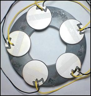 Finally, the ferrite ring with an outer diameter of 156 mm arrived. I
placed all four ordered mini horns on it. (Bottom, top, and both sides.) They
made a huge noise. However, the large magnetic ring did not react to this either. In the meantime, the mini horns equipped
with electronics arrived. Their square wave generator was set to 3.7 kHz, and
their volume was 105 dB. These did nothing either. Finally, I took out the 50
mm diameter and 3 mm thick piezo discs. I connected one of them to the signal
generator and tried to find its resonant frequency. It was a big disappointment.
Despite its enormous mass, it barely squeaked. How is this possible? Buzzers
with smaller diameter piezo discs make a
deafening noise, this does nothing.
Finally, the ferrite ring with an outer diameter of 156 mm arrived. I
placed all four ordered mini horns on it. (Bottom, top, and both sides.) They
made a huge noise. However, the large magnetic ring did not react to this either. In the meantime, the mini horns equipped
with electronics arrived. Their square wave generator was set to 3.7 kHz, and
their volume was 105 dB. These did nothing either. Finally, I took out the 50
mm diameter and 3 mm thick piezo discs. I connected one of them to the signal
generator and tried to find its resonant frequency. It was a big disappointment.
Despite its enormous mass, it barely squeaked. How is this possible? Buzzers
with smaller diameter piezo discs make a
deafening noise, this does nothing.
I sawed apart one of the mini horns. It turned out that the sound waves were not generated by the piezo disc, but by a thin brass plate that was glued to it. This metal plate, about 0.1 mm thick, was vibrated by the piezo disc. With this realization, I realized that it was not possible to make the 10 or 15 mm thick ferrite rings vibrate with sound waves. This would require kilowatts of energy, which would make such a noise that it would drive the neighbors away from the area. The sound of this generator could not be reduced to a tolerable level even if it were buried in the ground.
The 125 dB mini horn and the 105 dB one had a 25 mm diameter and 0.5 mm thick piezo disc glued onto a 35 mm diameter thin brass plate. The 50 mm diameter piezo disc would require a brass plate with a diameter of about 80 mm. I also found a similar alarm horn on the AliExpress web store. It said that its volume was 300 dB. I couldn't even try it because it would not only rupture my eardrums, but also shake my brain. Finally, I tried to directly vibrate the magnetic ring. I glued the 5 50 mm diameter piezo discs onto the 120 mm and then the 156 mm diameter ferrite ring. They froze completely. The large mass of the ferrite iron core did not allow them to vibrate. So much so that the Noise wave could not even make them vibrate. When excited by a noise wave, the current consumption of the 5 discs decreased to 6 mA, meaning they stopped completely. It was proven that permanent magnets cannot be made to vibrate with sound waves. Overall, this development also ended in failure. This is the fourth fiasco.
Budapest, March 15, 2025.
![]()
I'm getting tired of failures. I've been struggling with this issue for over a year now and have spent a lot of money on it. The result is zero. Now I have to resort to radical methods. But before that, I'll experiment even more with piezo discs. I'll try to pump more power into them. The signal generator's max. output current of 250 mA is not enough for this. Therefore, I connected the 5 piezo discs connected in parallel to the MOSFET amplifier. It didn't work. This is understandable. Transistors need a working resistance. If the drain electrode is hanging in the air, the amplifier won't work. And the piezo disc is a capacitive load, meaning it doesn't conduct direct current. The amplifier doesn't get power.
I looked around among the piezo disc excitation circuits and found several solutions. In one, a small resistor is inserted between the drain and the positive branch of the supply voltage, and the discs are connected in parallel to it. The amplifier then started working, but its efficiency became extremely poor. The resistor consumed most of the output power and converted it into heat. It seemed a more promising solution to replace the resistor with an inductance. In this case, there is no need to count on large losses, because the self-induction voltage of the coil balances the current dissipated by the inductance. As we saw earlier, voltage peaks of 70 V are also generated in the coil. The loss can be further reduced by a coil formed with counter-magnetic excitation. A large amount of free energy is also generated in this spiral coil, which is produced by the ether.
I have transferred the spiral coil of the Tesla generator here. In order to achieve greater efficiency, I chose the coil-in-coil version. Then I connected the 4 125 dB mini horns in parallel to the spiral coil. Starting from 10 Hz, I scanned the entire frequency range up to 15 MHz. Neither the 100 mm nor the 156 mm diameter ferrite ring responded to the excitation. Then I tried the 50 mm diameter 3 mm thick piezo discs. The result was the same. Since it seemed hopeless to make the large magnetic rings vibrate with sound waves, I thought that I should excite magnets of smaller mass. It also occurred to me that ferrite magnets have few magnetic domains. Therefore, I should try stronger magnets, e.g. neodymium.
I ordered a N52 strength magnetic ring with a diameter of 50 mm, and a magnetic disc also with a diameter of 50 mm. Their thickness was only 5 mm and 10 mm, respectively. Despite this, the low-mass magnets could not be made to vibrate either with the mini horn or the 50 mm diameter piezo crystal. It is clear that sound waves have no effect on the domains. Magnetic domains can only be moved with domains. And this requires mechanical movement. It is no coincidence that extraterrestrial civilizations also use this method. If there were a compact solution without moving parts, they would certainly have chosen it.
Budapest, March 30, 2025.
![]()
After the piezo disc vibration was finished, I took out the Keshe generator again. I can't stop thinking about what made this device work. Probably the coating made of various chemicals did not allow the magnetic energy to escape from the wire. After a while, this chemical dried out or decomposed, and the excess energy radiated from the spirals. Because of this, the device failed, and that's when the complaints began. I thought that I should try to generate excess energy with the spiral coils in another way. They should vibrate at a resonant frequency. For this purpose, I brought over the double spiral wound with 1.5 mm diameter enameled copper wire from the Tesla generator development. I connected it in series with my 800 W radiator. Nothing happened. Similar to the experiment with the small double spiral, the power consumption did not decrease this time either. This did not surprise me, because there is hope for this only in the case of oscillation at the resonant frequency. 50 Hz is too low for this.
To find the resonant frequency, you need a signal generator and an amplifier. Since alternating current must be regulated here, a MOSFET amplifier cannot be used here. You need a triac here. (A triac is nothing more than two diacs connected in parallel in opposite directions.) This way it conducts in both directions. This way, both the positive and negative periods of the sine curve can be regulated. However, it must be controlled with a direct voltage, for which a diac conducting in one direction is also suitable. The circuit that generates the control signal can be both complex and simple. The simplest one was developed by the Chinese. For this reason, the voltage regulator they sell is the cheapest. They recommend it for speed control of alternating current commutator motors, but it is also excellent for brightness control and temperature control of heating elements.
That's why I ordered a 5 kW copy from AliExpress. I connected it in series with the double spiral coil. Now I used 3 100 W conventional incandescent lamps as a load. The potentiometer brightness control worked perfectly between zero and full brightness. I measured it with an oscilloscope to find out what principle it uses to regulate.[71] My suspicion was confirmed, it is a phase-splitting regulator. It cuts slices of different widths from the sine curve. This reduces the effective value of the voltage. Well, that's not good for us. We need frequency converter regulation here. We have to map out its circuit diagram, then disconnect the internal control circuit from the diac and replace it with a function generator. Fortunately, we are free from this time-consuming and patience-requiring work, because someone else has already done it for us. Walter Reéb explains in detail how the circuit works in his video uploaded to YouTube, and also shows its circuit diagram.[72] This circuit is found in all Chinese speed controllers. The only difference is in the type of triac. While the 5 kW model has a 40 A BTA41-600 triac, the 2 kW model has a 25 A BTA24-600 triac.
Based on the circuit diagram in the video, it is no longer difficult to change the control. Since I was afraid of the peak voltage of 320 V in my signal generator, I installed a cheap square wave generator with an NE555 integrated circuit. (These can also be purchased from the AliExpres online store, in several versions.) However, the delivery of the high-current BTA41-600 triac will have to wait. The high-current diac will also arrive in early June, which will be needed for further development of the Tesla generator. Honestly, I do not have much hope for the continuation of either development. The large spiral coil of the Keshe generator has a low probability of vibrating at the resonant frequency. This is because it does not have a resonant frequency. As a result of the reverse excitation, its transverse wave emission has ceased. Magnetic radiation cannot transform. Moreover, it cannot induce a resonant frequency.
This can be clearly seen from its behavior in the Tesla generator. Excited from 10 Hz to 1.5 MHz, there was no jump in the amplitude of the self-induction voltage peaks at any frequency. However, resonance was already induced in the air-core coil placed on it. The amplitude of the induced voltage increased threefold at about 240 kHz. The large spiral coil inserted into the Keshe generator will probably be able to do this, but the voltage induced by it cannot generate the current we need. This performance is far below the desired 5- or 10 kW. Such power can only be extracted from plasma generated by condensed etheric particles. And the Keshe generator will never produce plasma. This goal must be achieved by another means. However, this means is quite expensive. I cannot finance it.
Budapest, April 28, 2025.
![]()
However, resonance frequency excitation can still produce extra energy. After the triac arrived and the DIAC I took out my mini rectangular generator and then dismantled my 5 kW phase voltage controller. I disconnected the control circuit from the DIAC and turned on the rectangular generator through a 100 Ω current limiting resistance, which I fed from a 5 V voltage stabilizer. I injected the device into the mains of the mains power phase, and as a load, I tied 3 pieces 100 W incandescent lamps in parallel. Nothing happened after turning it on. The lamps remained dark. Ringing with an oscilloscope, it turned out that there was no tension on the Triac Gate electrode. Diac ate. I raised the supply voltage to 12 V. Then the triac was completely opened and did not react to the control. In addition, the background phase circuit circuit generated all kinds of noises.
Therefore, I assembled the voltage controller and took out the tubular disc used for the board model and built a separate circuit with a new triac. Here I left the DIAC and fed the rectangle generator with 5 V. The output was connected through the 100 Ω resistance to the high-current BTA41-600 triac gate electrode. I soldered the ground point on the leg of the triac A1. It became the output of the circuit and the input became the leg of the triac A2. This circuit has already worked. But my pleasure didn't last long because he did strange things. At low frequency (some Hz), the lamps flashed. Increasing the frequency were flashing. I already thought I had made a high -flow frequency cure curer. However, in terms of 50 Hz and the negative semi-period of the sinus wave, the frequency regulation stopped to 100 Hz.
Studying the oscilloscope figures, it turned out that the rectangular generator did not regulate the frequency, but to multiply the switching on and off. In the positive range of the rectangular signal, he passed the 50 Hz current and closed it for the break. In this way, he passed signal packages on Triac. Towards 50 Hz, the signal packs then touched and a continuous 50 Hz sinus wave on the oscilloscope. After that, even though I raised the frequency of the rectangular generator, nothing happened. I was raised that the causes of the incomplete lamps were the reason for this. The wolf thread is approx. He blinked up to 25 Hz. Then he was constantly lit. So I replaced them with an LED lamp. The LED can withstand connecting very well. It even operates in Gigahertzes, even for years. Here, too, he flashed fast. Even after the signal packs were closed, it blinked, but this compilation could not raise the 50 Hz frequency.
It has been confirmed that the triac is not a transistor but a switch. Controlled diode. You can only reduce the frequency of the current connected to it by the multiplication of the switching, not to increase it. When the switching multiplication reaches the power frequency of the mains, it will open completely and flow through it unhindered. Only the network can change the power frequency. If the mains current were 1 kHz, it would switch it. Increasing the operating frequency cannot be achieved with the control mark given to the Gate electrode. This can only be achieved with the negative voltage given to the triac. This occurs 100 times per second on the 50 Hz mains voltage. Even though I increase the control of the control voltage to several kilorarts, the triac does not receive closing voltage at this frequency. The triac would probably be able to switch hundreds of kiloharzen if it would close it.
This way I could not determine the double spiral resonance frequency because the triac is not an amplifier, but only a valve. In addition, the EMI radiation was quite large. He was very disturbed by analog radio. (However, this switch, blinking for something, is perfect for blinking between 1 Hz and 50 Hz at any frequency of up to several kilowatt lamps. There is no need for a relay. A few dollar parts can be built without moving parts.) If we don't want to get a fatal electric shock, don't forget to use electrician's rubber gloves while working!
I have only one option left for frequency-dependent voltage regulation: PWM regulation. I am curious about what pulse width regulation is capable of. However, this circuit operates on DC voltage, so I return to the development of the Tesla generator. I am forced to stop the development of the Keshe generator because it failed again. This is the fifth fiasco in the development of resonant frequency. Despite this, I will not give up the fight. However, to move forward, money and professional cooperation would be needed, but neither is coming to me. Not least because almost no one knows about my activities. Some people really don’t like my work, because my library has hardly had any visitors for two years. Both of my websites have been blocked. If I go to a library and click on one of my websites, I receive the following message: “Bitdefender Endpoint Security Tool blocked this page.”
My readers in the Hungarian Electronic Library cannot access the latest version of my works either. The government’s censorship office does not allow them to update them. The latest version of my cookbook has been waiting for an update for 1 year. Initially, the administrator replied to my urgent letter that the National Széchenyi Library's collection is currently being digitized, and that this is more important than adding new books. After this is finished, they can't think of anything, so they don't respond to my letters of inquiry at all. I just don't know what the censors don't like about a cookbook. What threatens those in power, potato soup or pumpkin stew?
Years ago, the Prime Minister and his ministers called me a quack and a charlatan, and told me that they don't support crooks, especially not with taxpayers' money. Until then, I thought I was a development engineer, but in the meantime I was reclassified and completely paralyzed. Today, esotericists are no longer murdered like they were 100 years ago. Instead, they found a more effective method, financial imposture. The renegade must be deprived of all income. In the current money-oriented world, those who have no money cannot move. They become incapable of action.
Meanwhile, global warming has gone into full gear. Last year, spring frosts took away half of the fruit crop, and as a result of the drought, the corn and sunflower fields in the Great Plain withered. This year, 80 percent of the fruit crop was destroyed, and farmers are already lamenting that if there is no rainfall in June, we can say goodbye to the entire corn and sunflower crop. And people are dying en masse worldwide in the 50 °C heat. (According to extraterrestrial civilizations, we will burn alive.) This process could be stopped by weather control and rainmaking, but this is quackery, it should not be done. Anyone who tries such a thing should be trampled. The world would rather be destroyed, but even then we don't need the help of charlatans.
Budapest, June 21, 2025.
![]()
In retrospect, the previous method of electromagnetic excitation was hopeless. A permanent magnet is created by magnetizing an iron core with a powerful electromagnet. Like all electronic devices, an electromagnet is operated by transverse waves. So when I applied current to the wound permanent magnet ring, it did not attract the domains to the center, but rather squeezed them to the two sides of the ring. However, magnetic domains attract and repel each other. (This is what causes two permanent magnets to stick together and repel each other.) So when we move two magnetic rings above each other, the domains swirl around in them. However, this alone is not enough to displace the etheric particles flowing into the ferrite ring.
To do this, they must be brought into resonance. Here another physical phenomenon comes into play, which many did not think of when they wanted to build the Hamel generator. Only a few of the thousands of bloggers reported success. This physical phenomenon is also created by the ether, and the aluminum cones floating in the magnetic field transmit it to the magnetic rings. The ether not only fills the universe, but also swirls. This vortex-like flow sets the aluminum cones in motion, vibrates. This would still not be enough to direct the domains to the center, and condense and squeeze them out of the ring-shaped magnet.
By vibrating the upper magnet, the direction to the center is already achieved, but for the condensation, the lower magnetic ring must also vibrate. This is also done by the ether. The ether waves also flow into the lower magnetic ring, so the meeting of the two waves triggers a resonance in it, which then compresses it and squeezes the etherons out of it. Since the ether cannot tolerate vacuum, new etherons flow into the lower magnetic ring, so the process becomes constant, and the antigravity effect is created. The excitation can only be stopped by preventing the movement of the aluminum cones. This concentrated energy radiation creates plasma, which can be used to produce large amounts of electricity. As already mentioned, the American Chris Felton has already done this.
But I can't do it, because building the Hamel generator requires a well-equipped machine shop. Deep-drawing, cutting, and injection molding tools, the design of which costs hundreds of thousands. Without support, I can't afford these costs. If I had the money, I wouldn't do anything with it, because industrial companies don't negotiate with private individuals. In order to be able to negotiate, I would have to set up a laboratory. However, setting up a company costs millions.
It's very annoying that I've been working on sub-electronics developments for years and haven't achieved any results. Moreover, I've ruined myself financially. However, this series of failures was good for me to gain professional experience. Based on this, I realized what was the reason for the fiascos. I wanted to achieve success using the usual methods in electronics. Ethereal particles cannot be condensed or concentrated with electrons, photons, or sound waves. Only magnetic domains can do this. In order to do this, physical principles that we do not know must be applied. One of these is counter-magnetic excitation, which many people talk about, but no one can apply purposefully. Even the best experts in this field have only achieved partial successes caused by chance.
The reason for this is that we are not aware of its working mechanism. Therefore, we cannot reconstruct the free energy generating devices of Tesla, Moray, and other inventors. Since the society of 80-100 years ago did not claim their inventions, they took their secrets to the grave with them. Now we desperately need the results they achieved, but it is too late to regret. Our punishment is that we have to start from scratch.
It won't be easy, because we're already hitting a snag at the very beginning. We don't know what magnetic domains are. Physicists say they're miniature magnetic islands found in paramagnetic materials. They're tiny magnets that emit etherons on one side and gravitons on the other. These microminiature particles that make up the universe penetrate all paramagnetic materials, but what keeps them there? The Creator trapped them, but how? We're not surprised that they radiate Yang and Yin rays for decades, because radioactive materials do the same. There's an isotope with a half-life of 1.405 × 10¹⁰ years.
Since the domains are bipolar, the permanent magnets they create also become bipolar. Under the influence of electromagnetic excitation, they align in one direction and, multiplying their strength, radiate Yang and Yin energy. These two energies are not separated, but are connected to create lines of force around the permanent magnet. Unfortunately, this connection is harmful to us, because the speed of their radiation is reduced to the speed of light. And we would need longitudinal waves with a speed 12 orders of magnitude higher. They would also have to be condensed.
It is also unclear what constitutes magnetic lines of force. Since they propagate in the ether, we could think that ether ions are used as a carrier medium. But then why is their propagation speed so slow? (See the speed of electromagnetic waves emitted by radio, television and other microwave transmitters.) This slowness suggests that photons constitute the carrier medium. However, this cannot be, because then electronic communication would stop in the dark. Scientists should solve these dilemmas, but they do not have time to do so, because they are currently engaged in nonsense. They would have something to think about, because, for example, we do not even know what electrons are made of. Despite this, we have been using them for 200 years. Now we will do the same with concentrated ether radiation called vril. Assuming we succeed.
Vril is a completely unknown type of energy to us. It is the purest and most intense energy in the universe, and it is free to use. Civilizations far more advanced than ours know of several ways to produce it. One of these is the splitting of element 115 into element 116. (Under the influence of proton radiation, moscovium turns into livermorium, and in the process it emits a huge amount of ether ions. Their number is so large that they leave the crystalline drive in a concentrated form, in the form of vril. (The disadvantage of this drive is that it is sensitive to shock. If it is hit, it explodes with such force that it causes even greater destruction in the environment than an atomic bomb.) In addition to this, there are at least a dozen antigravity drives. The number of those available to us is not small. Based on our experience so far, let's stick with the vril that can be expelled from magnets.
We can extract concentrated ether ions from these in three ways. The physical basis of all three methods is opposite magnetic excitation. The existence of this physical law was revealed to us by the "little grays", but they did not tell us more about it. So we had to figure this out too. One method is to vibrate two magnetic rings that are attracted to each other. (See Hamel generator.) The other is that two magnetic rings are rotated in opposite directions by a motor. The third is electromagnetic excitation. (This solution is advantageous because it contains no moving parts and is cheap.)
I tried this before, but I failed. The mistake I made was that I did not provide for the opposite excitation. First, I excited a transformer iron core, then a permanent magnet. However, this only increased the strength of the permanent magnet. As mentioned earlier, vril never flows out of the electromagnet. (The current most powerful electromagnet in the world is an extremely expensive superconductor. It is 1 meter long and weighs several tons. Its coil is made of 13 km long niobium-zinc alloy wire, which becomes a superconductor when cooled to 4.2 K. It is capable of a field strength of 14.7 Tesla. Despite this, it does not squeeze out a single spark of etheron. It doesn't even move.)
To do this, you need to bring the permanent magnet into resonance. According to an Internet source, this requires two coils placed on top of each other, with a separate power supply and a square generator. The other solution is to use a bar magnet. When wound with thick wire and using a strong current, the domains are already willing to concentrate the ether ions flowing into the magnet. However, its strength is only enough to start the opposite magnetic excitation when turned against another coiled magnet rod. This method was used by Hans Kohler, who worked in a development institute of the German army during World War II.[73]
However, the plasma produced by two coiled magnet rods is not enough to lift a multi-ton vehicle high. This requires at least 6 magnet rods, and the vril they generate must be summed. He achieved this by enclosing magnet rods. (He shaped them into a honeycomb shape.) This is how you can use an antigravity drive received, but had a lot of trouble starting it. For plasma formation, an air gap was needed between the bar magnets. However, the size of the air gap was not precisely determined, so it took minutes to revive the system by moving the bar magnets and setting the resonator coils in different positions. However, this statement is a false assumption that appeared in UFO publications. This is what is written about it: “Based on Captain Hans Kohler’s Tachyon converter and using the knowledge gained from the Vril system, the RFZ-4 antigravity spacecraft was completed in 1944.”
There is no indication that the Tachyon converter was the antigravity engine. This role was probably played by a mercury circulation engine. It was not for the German researchers to develop this, because an extraterrestrial civilization living in the Aldebaran star system sent them a bell with Sumerian inscriptions that was able to fly on its own. The mercury-filled Glocke was a 3-4 meter high and wide metal bell that served to model the operating mechanism of the engine. The Tachyon converter probably supplied the vehicle with electricity. According to one report, the power of this generator at 12 V was 6 kW, which would be enough to power a large household. Unfortunately, the device was destroyed in an air raid in 1945.
Since we need a free energy generator, this should now be reconstructed. It will not be easy, because I can only count on myself again. Before I set out to reconstruct the Kohler shape, I asked the artificial intelligence what it knew about the subject. My question was: “How does Hans Kohler's anti-gravity engine work?” The answer was: “There doesn’t appear to be any verified information about an anti-gravity engine developed by someone named Hans Kohler.”
It will be quite difficult to measure the formation of vril. The longitudinal wave created by etherons is not a magnetic wave. For this reason, it probably does not attract the south pole of a compass. The compass of a cruise ship does dance back and forth when a UFO flies over the ship, but this can be attributed to the fact that the vril comes from a permanent or electromagnet. Magnetic generators retain their magnetic radiation while concentrating the expulsion of ether particles. However, there is no magnetic wave in a crystalline engine. Does the vril emanating from it attract the compass needle? There is no reference to this in the literature.
However, there is also a futuristic method for measuring vril, time dilation. According to esoteric literature, time slows down near strong Yin radiation. And it speeds up near strong Yang radiation. What I will do is set my old spring alarm clock inside the hexagonal shape and write down the hours and minutes it shows. Then after an hour I will compare it with the time shown by my alarm clock radio. It will be an interesting experiment. The question is whether I will manage to get there or whether it will be a sixth failure. Unfortunately, time dilation is not suitable for measuring the strength of vril exactly. This can only determine that longitudinal waves, not electromagnetic, are flowing from the generator. An instrument similar to a gravimeter would be needed to measure the strength of gravitational radiation. However, we cannot find one. We search the literature and the Internet in vain. Artificial Intelligence is no help either.
If we ask Artificial Intelligence: What is vril energy? – it answers: “Vril energy is a fictional, omnipotent life force. The term has also been adopted by occultists and is a recurring theme in conspiracy theories, although it has no scientific basis.” Since this is my many failures with using AI, my opinion is that we will not get far with the deified Artificial Intelligence (AI). It lives off what it steals from various places. It has no idea about cutting-edge technology. If someone tries to enlighten it, it replies that it cannot take this source into account. Then it notifies the development center. However, the developers of artificial intelligence are not even willing to look at the recommended literature.
However, AI is excellent for forgery and fraud. That is why it is currently a favorite toy of criminals. He uses his huge server park to produce fake photos and misleading documents in droves. His moral sense is zero, so he can be tricked into doing any evil deed. Despite this, the great powers want to pour hundreds of billions of dollars into the development of AI. They would be better off if they spent this money on the development of cutting-edge technology and a paradigm shift.
In this situation, I can only rely on myself. Well, then let's start experimenting. It will be a great adventure, because I have no idea how to do it. Captain Kohler probably started the development this way. All he knew was that excess energy can only be extracted from where it is. Energy locked in matter is only in radioactive materials and permanent magnets. Releasing radioactive energy is quite dangerous and expensive. Building a nuclear power plant consumes billions. It is no coincidence that most countries are trying to get rid of their existing nuclear power plants. However, unleashing magnetic energy requires an investment of only a few hundred dollars.
It is no coincidence that Kohler also started in this direction. The next step was to determine what shape of permanent magnet to use. He needed a magnet in which the magnetic force of the domains is concentrated on a small surface. To displace the etherons, a high magnetic field strength is needed. A bar magnet is such a shape. He certainly tried several shapes and found the bar magnet to be the most suitable for this purpose. That is why we should also start in this direction. Since no information has been made public about the structure of the Kohler generator, we can only guess what length and diameter of the bar magnet he used.
 A bar magnet that is too thick and long is expensive, and a short and
thin one is weak and cannot generate plasma
radiation. Therefore, I made a medium-sized honeycomb shape from
discarded cooking spoons. From this it turned out that a bar magnet 100 mm long
and 10 mm in diameter would be the most suitable for us. They do not
manufacture 100 mm long bar magnets, but this problem can be easily overcome
by gluing two 50 mm long ones together. (This will not make the bar magnet
stronger, but it will allow a larger coil to fit on it, which will increase the
induction.) Use epoxy resin to glue the bar magnets together. Apply just enough
of this extremely hard two-component glue to the end of one of the bars so that
it does not stick out when the two bars are joined together. (The glue takes 24
hours to dry rock hard.)[74]
A bar magnet that is too thick and long is expensive, and a short and
thin one is weak and cannot generate plasma
radiation. Therefore, I made a medium-sized honeycomb shape from
discarded cooking spoons. From this it turned out that a bar magnet 100 mm long
and 10 mm in diameter would be the most suitable for us. They do not
manufacture 100 mm long bar magnets, but this problem can be easily overcome
by gluing two 50 mm long ones together. (This will not make the bar magnet
stronger, but it will allow a larger coil to fit on it, which will increase the
induction.) Use epoxy resin to glue the bar magnets together. Apply just enough
of this extremely hard two-component glue to the end of one of the bars so that
it does not stick out when the two bars are joined together. (The glue takes 24
hours to dry rock hard.)[74]
The next day, insulate the bar magnets with wide Mylar tape so that the winding wire does not touch the nickel coating and cause a short circuit. The big dilemma is what diameter of enameled copper wire to use for winding. It would also be good to know how much of it to wind on it. The only thing that is certain is that a strong electromagnet requires a lot of current, which can be created with a short and thick wire. First, let's try a 1 mm diameter winding wire, which we form in one layer on the magnetic bars. (Leave a strip of about 6 mm wide free at both ends of the bar. If plasma formation starts, the excitation coil cannot participate in it.)
Since we have to start from scratch, let's first see if the electromagnet is able to increase the field strength of the permanent magnet. Since the internal resistance of the single-layer coil is about 0.1 Ω, and the 1 mm diameter copper wire can withstand a maximum current of 5 A without heating up, we should carefully excite it. First, turn on a direct current and see if it increases the field strength of the magnetic bar. The easiest way to do this is to place a compass in front of it. When placed close to it, the magnetic bar attracts the south tongue of the compass. Move the compass away until its black tongue points towards the Earth's north pole. Now we turn on the stabilized power supply and, starting from zero, carefully increase the voltage until the coil starts to heat up. Let's see what the compass shows. If it starts to attract the south tongue, then we have won, because with this assembly we can already make a magnetic wave generator.
However, we need condensed ether beams that cause a much more intense effect, which initially do not cause plasma formation. How do we measure this? Concentrated ether beams that propagate in the form of longitudinal waves are not magnetic waves. However, when extracted from permanent magnets or electromagnets rotated in the opposite direction, they can contain magnetic waves. This way, perhaps they will be detectable. By the way, the crystalline drive can also be considered a cold fusion power plant. Currently, our scientists are spending billions of dollars on a fusion power plant that creates a large one from two smaller atomic nuclei by merging them. (This process also occurs in the Sun, under natural conditions.) However, under artificial conditions, this requires a temperature of 100 million °C and a pressure of 100 thousand atmospheres. Meeting this requirement is very difficult and expensive. At this temperature and pressure, the electrons of the gas atoms are torn away from the atomic nucleus, and the gas turns into a mixture of electrically charged atomic nuclei and electrons, called plasma.
In the process, a large amount of heat is released, which is then converted into electrical energy using technology from the age of steam locomotives 200 years ago. First, water is boiled, and the resulting steam is used to drive a steam turbine. A power generator is attached to the shaft of the steam turbine, which finally creates electrical energy. Due to the multiple conversions, the efficiency of this method of electricity generation is only 33%. The aliens use cold fusion to generate energy, which is almost 100% efficient and has minimal production costs. In the crystalline drive, they make a larger one, 116, from the element with atomic number 115. This is also fusion. All you need for this is a large solenoid in which the ether waves generate electricity. However, our scientists are not interested in this type of energy generation because it is not complicated enough, you cannot write a doctoral dissertation on it. By the way, bombarding the nucleus with a proton beam is also suitable for material transformation. Much cheaper than the way physicists currently produce gold from mercury in nuclear power plants, for demonstration purposes.
Exciting the magnetic bar with direct current did not bring any results. And it was done with a lot of current. I connected 0.8 V to the 0.1 Ω coil. So 8 A flowed through it, which is not a lot. Despite this, the compass did not react to it. The magnetic radiation of the magnetic bar did not increase. I reversed the direction of the current, nothing happened. I took the other coiled magnetic bar and connected it in series with the coil of the previous bar. I brought the two magnetic bars together. It did not react to this either. I separated the two magnetic bars and turned one of them over. At that time, they repelled each other, but this time nothing happened either. Then I excited the two coils in parallel. They did not react to this either.
This is understandable. All I did was create an electromagnet. In the case of an iron rod, this coil would have magnetized the rod, but here it did nothing. The neodymium rod is magnetized with a strong electromagnet, which aligns all the domains in it in one direction. These small coils could not increase the magnetic radiation of the rods, because there were no more domains that were out of orientation. It might be possible to repolarize the magnetic rod, but this would require a much stronger electromagnet.
The accurate measurement was somewhat hindered by the fact that the ammeter display of my 20 A 30 V power supply was inaccurate. It showed 10% less current. I wrote a letter to the Chinese online store asking how I could correct the error. They did not respond. I asked them to send it to the manufacturer if they did not know the answer. Hongpoe did not respond either. I thought I would write to the factory directly. I found their email address on the Internet, which was the same as the webshop. They have their own webshop. The circle was closed, it seems they do not engage in correspondence. At that time I used the chat window. We had a cordial discussion. In the end, their employee said that he would forward my complaint to their development department. He asked for my email address, but I waited in vain for a response. Warranty repairs are not fashionable in China. They do not deal with such things.
The failure of electromagnetic excitation with direct current did not surprise me. I knew that I would not get anywhere with this. Resonance frequency excitation requires a frequency generator. The high-performance function generator developed for the Tesla generator came in very handy for this. I would not get anywhere without it. The max. 250 mA output current of signal generators is not enough for anything. After assembling the received modules, I received a square wave generator with a load capacity of 20 A, which will hopefully be enough for plasma formation. However, this is a long way to go, and success is not guaranteed at all. It can be quite an obstacle if the resonance frequency of the magnetic bar is above 150 kHz. In the current configuration, the high-power frequency generator only works so far. The Miboxer company would be willing to develop a controller that can be used from 1 Hz to 1 MHz, but they will only do this if I order at least 1000 of them. I will never have that much money.
Resonance frequency excitation was a problem from the start. It turned out that I couldn't excite the bar magnets with this thick wire. If I connected 6 magnets wound with 1 mm diameter copper wire in series, their resistance would still only be 0.6 Ω. Although 1 mm diameter copper wire can handle 5 A without heating, this current is already generated at a supply voltage of 3 V. However, the MOSFETs start to open at 5 V and operate without heating at an excitation voltage of 9 V. Due to the 50% duty cycle of the square wave, the supply voltage can be increased to 6 V, but this would still result in unstable operation. Therefore, I used Ø 0.5 mm enameled copper wire to wind the 6 bar magnets. When connected in series, their resistance was 3 Ω. At a supply voltage of 3 V, 1 A flowed through them, which they tolerated without heating. When measured with a compass, the radiation of the 6 magnetic bars did not increase in this case either. I connected the square wave generator, the signal of which I amplified with MOSFETs. Now at a supply voltage of 10 V, 2 A flowed through the 6 coils connected in series. This made them warm, but the magnetic field strength radiated at both ends did not increase either.
I started to increase the frequency, in case the magnetic bars would resonate somewhere. Their magnetic radiation did not increase either. Due to the inductive load, 16 V self-induction spikes appeared at the beginning of the square wave. When measured between 1 Hz and 150 kHz, I did not experience resonance anywhere. However, above 60 kHz, the signal shape became so distorted that the MOSFETs also started to heat up. Converted to a sine wave, maybe I'll get lucky there. It didn't. The sine wave was completely distorted. The power amplifier cut off the positive half-period of the sine wave. They were willing to amplify it properly with a CMOS wave with a parallel-connected MOSFET that only had a positive range.
Well, let's see how the 6 magnetic bars behave in a honeycomb pattern. I found a 2 mm thick textile bakelite sheet measuring approx. 25 ×25 cm, and glued the 6 wound magnetic bars onto it in a honeycomb pattern. I used wide cellux tape to attach them. It wasn't difficult to glue them together, because I now fitted them together so that they attracted each other. Since the 6 magnetic bars formed a closed circle, I couldn't check their operation with a compass. So I placed a multi-turn solenoid in the middle and connected the oscilloscope to the two wire ends. I also tested this between 1 Hz and 150 kHz. There was no resonance anywhere. The oscilloscope only showed ether noise and EMI radiation leaking from the environment. This was revealed by a sine wave with an amplitude of 1-2 V that appeared on the display. There was some resonance at 50 kHz and 100 kHz, but I did not see any trace of the square wave used for excitation.
The possibility arose that I would grind the ends of the bar magnets at 30° and glue them together, similar to a honeycomb structure made of wooden sticks. The disadvantage of this is that the structure of the magnetic field at the end of the ground bar magnet is damaged. The lower we examine the lines of force, the weaker they become. Overall, the ground magnetic bar creates a lower field strength around itself. The other disadvantage is that if there is no air gap between the bar magnets, plasma cannot form between them.
So let's try reverse excitation. In this case, I connected the end of the coil of every second magnetic bar not to the beginning of the coil of the next magnetic bar, but to the end. In this way, I created a bifilar winding, which does not deteriorate, but even increases the efficiency of the excitation, because it cancels out electromagnetic radiation. This creates magnetic radiation, which is clearly advantageous here. However, practice did not confirm the theory. The 6 magnetic bars remained paralyzed again. Neither plasma nor measurable radiation was formed. I also scanned the frequency band up to 150 kHz. I did not experience any change.
I thought there was a problem with the way the magnets were aligned. Therefore, I inserted every second bar magnet in the honeycomb shape in reverse. It was extremely difficult because they repelled each other. They kept loosening the cellux tape. I was only able to measure this arrangement with great difficulty. The result was disappointing. Nothing happened this time either. The bar magnets did not emit even a few mV of magnetic radiation. It is not possible to create magnetic excitation in opposite directions with magnets that repel each other. (In the Hamel generator, the two magnet rings are also inserted in mutual attraction. Their adhesion is prevented by granite balls, which create a distance of about 5 mm between them.)
Since I didn't know how to get out of this dead end, I started searching the Internet, hoping to find some information, a starting point about the Kohler generator. Even Google search couldn't help me with this. However, this topic was discussed in Chapter III of the dissertation entitled The Free Energy of God. However, this obscure dissertation is just fiction. Its author tried to figure out how it worked. He mixed all kinds of scientific principles into his extremely complicated explanation, which most likely had nothing to do with reality. However, this also seemed good as a starting point. He confirmed that the Kohler generator was made of bar magnets, which were excited as electromagnets. The description also mentioned magnetic excitation in the opposite direction. I'm over that too, it didn't help either.
Finally, the author mentioned the need for a second excitation coil, which should be made of thin enameled copper wire, with as many turns as possible. These coils must be connected in parallel and connected to the square generator. At first glance, this solution did not seem very effective, because so little current passes through the thin wires that it does not significantly increase the excitation. The magnetic flux, however, increases with increasing the number of turns. However, this is not its role here. The back-and-forth pulling of the electrons due to the counter-directional excitation increases the number of free electrons in the coil, on the one hand, and on the other hand, it moves the domains in the bar magnet. The secondary coil increases this chaos by creating unidirectional excitation in each coil. The turbulence caused by the electrons being pulled in a chaotic manner also causes the domains to vibrate. Since the domains are an order of magnitude larger than the electrons, they are able to push the etherons out of the two ends of the bar magnets. However, the ether sea does not tolerate vacuum, so new etherons flow into the bar magnet, which are pushed out again by the disturbed domains.
So let's see if the two-coil solution works. According to the treatise entitled The Free Energy of God, the secondary coil should be made of thin wire, and as many turns should be wound on it as possible. However, I ran out of Ø 0.1 mm enameled copper wire. I only had Ø 0.2 mm available, and that too in limited quantities. So only 20 grams were available for each bar magnet. (I give the secondary winding number by weight because DIY winding machines can only attach a coil body, not a metal rod. This way, you have to wind the magnetic rods by hand. It is also not practical to monitor the number of turns, because there are a lot of turns on it, and you can lose count. Put the magnetic rod with the primary coil on a small piezo-disc scale and weigh it. Then wind it until its total weight is +20 grams.)
Before we start winding, cover the primary coil with Mylar tape to avoid short circuits. Now we assemble the completed magnetic rod electromagnets in a honeycomb pattern. The 6 secondary coils must be connected in parallel to each other. We check the result with an ohmmeter. If we have measured the weight accurately, the resistance of one coil will be 40 Ω. When connected to each other, their resulting resistance will be 7 Ω. After that, I connected the primary coil in parallel with the secondary coil. Their resistance decreased to 2 Ω. The only consequence of this was that the current consumption of the coils increased to 2.5 A, and the self-induction voltage peak increased to 60 V. I did not expect any other reaction, because in fact I did nothing more than make a stronger electromagnet. However, one coil cannot move the domains. To do this, the two coils must be brought into resonance.
First, I disconnected the secondary coil from the primary coil. Then I excited both coils from a separate signal generator. I increased their 250 mA signal with two high-current, MOSFET transistor amplifiers. First, I excited both coils with a 1 kHz square wave. Their total current consumption became 2.5 A, that is, it did not change. The only change is that the self-induction voltage on the multi-turn secondary coils has increased to 80 V. So let's scan the entire frequency band to see if we can find the resonant frequency somewhere. Let's start at the beginning of the band. I set the frequency of the multi-turn secondary coils connected in parallel to a fixed frequency.
I started the excitation at 10 Hz and started increasing the frequency of the primary coil in small steps. I did not notice any resonance anywhere. After 10 Hz, the setting was 20-30-40 Hz, and so on. In the kHz range, I went up by 10 kHz with the other function generator. I did not notice any amplitude increase anywhere. Maybe their resonance frequency is above 240 kHz, but I did not get any further because the MOSFET amplifier stopped at 240 kHz. (MOSFETs cannot handle fast switching. A PWM controller would be needed for their high-frequency control. The Chinese company Miboxer would be willing to develop a controller that works up to 1 MHz, but only if I order at least 1000 of them. Since it would cost about $6, I would have to raise $6000 (2 million forints) for this. Where can I get that much money? The lack of a PWM controller had its detrimental effect even in the middle of the scale. Above 60 kHz, the square wave signal was strongly distorted. It became a sawtooth signal, and its amplitude also decreased. This also reduced the chance of finding the resonant frequency.
For the sake of order, I also performed this test with reverse control. As we know, the magnitude of the flux depends on the size of the inducing surface. Since the surface of the multi-turn secondary coil is much larger than that of the single-row primary coil, it generates a large magnetic field even at low current. This causes intense induction changes creates in the iron core, in this case in the magnet bar. Knowing this, I now set the large diameter primary coil to a fixed frequency and used the multi-turn secondary coil to perform the excitation. First, I set the primary coil to 1 kHz and scanned the frequency band with the secondary coil in the same way as before. The test between 10 Hz and 240 kHz did not yield any results either. I did not experience resonance anywhere. Then I set the primary coil to 100 Hz and scanned the frequency range again. The result was the same.
It is also possible that the magnetic induction is small. Stronger electromagnets would be needed to move the domains. A 1 mm diameter wire would be needed for the primary coil, and much more, 40-50 grams of copper wire, would be needed for the secondary coil. However, the price of copper, like that of rare earth metals, has skyrocketed. escaped. That's why I can't order more enameled copper wire. The arrangement of the coils can also cause problems. To fix them stably, a honeycomb-shaped cradle made of white bakelite would be needed. In order to make winding easier, it is advisable to wind the two coils on a spool also made of white bakelite. The inner diameter of the spool should be designed to be 10.5 mm and the wall thickness to be 1 mm. It is advisable to close the two ends of the spool with 1.5 mm thick discs. The electromagnets glued into the grooves would not be able to move forward, backward, or sideways. An identical upper cradle would have to be glued onto the lower cradle, which would prevent the electromagnets from moving upwards. These shapes require injection molding tools to produce, each of which would cost hundreds of thousands of forints. Prototypes could also be produced with a 3D printer, but this is not cheap either.
However, the operation of this would not guarantee it. Finding the resonance frequency is an extremely time-consuming activity. One person is unable to do it. This would require at least half a dozen employees (development engineers, technicians, electrical engineers). Today, it is impossible to find usable labor for a monthly salary of 1 million forints. To employ that many people, a laboratory would have to be established, which would require several million forints of start-up capital. Then, if the development is successful, we will put the result on the Internet, from where anyone can download it for free. They will not even be interested in supporting us. If we do not upload it to the Internet and start manufacturing it ourselves, we will not achieve anything. They will buy a copy, copy it, and start manufacturing it illegally. Today, they do not buy inventions, they steal them.
The British Intelligence Objectives Sub-Committee[75] report revealed that Kohler also suffered a lot during the development of this generator. Hans Kohler invented his generator in 1933. The first version was only a few hundred mV voltage and a few hundred mA of additional current. This was only possible after a long tuning. The coils were moved back and forth on the magnetic bars, which were first 6 mm and then 8 mm apart. The additional energy often appeared only after half an hour of waiting. (Hamel also experienced this phenomenon with the antigravity drive named after him.) The complicated tuning can be attributed to the fact that in the 1930s and 40s there were no semiconductors yet. Therefore, they did not have a signal generator. The square wave signal was produced with a mechanical chopper. (A Bosch ignition magnet motor breaker was used as an opening-closing switch.) They used a cathode ray tube as an oscilloscope, without any markers or calibration options. Their voltage and current meters were also quite rudimentary.
Despite this, his work was of great interest from the beginning. The fascist dictatorship was in great need of free energy without chemical or mechanical energy sources. (Their army suffered from a constant fuel shortage after the outbreak of World War II.) Therefore, their officers visited and interrogated Kohler. After they were convinced that it was not a fraud, the research department of the O.K.M. sent sufficient instruments and parts for further development. However, this was hindered by the fact that they did not know the operating principle of the generator. And if someone does not know the operating principle of the device they want to develop or reconstruct, they will not succeed. This greatly hindered the start of series production.
Therefore, on the orders of Hermann Göring, scientific professors, physicists, and electrical engineers were sent to Kohler's laboratory to provide him with theoretical assistance. Their unanimous opinion was: “Hans Kohler has developed a device for generating electrical energy that provides a significantly higher electrical power than was required to excite the primary fields of the device.” Seeing the unusual circuit solutions, they stated: “With our current knowledge, we cannot explain the way in which the excess current is generated.” Therefore, they asked the inventor for clarification.
However, their questioning was fruitless, since Kohler could not give a satisfactory explanation. He did not know the operating principle of the circuit. He said things like: “The effect of high-frequency, pulse-like field changes on the movement of electrons in pre-magnetized steel bars through the oscillations of the molecules of the magnets.” His only valuable statement was: “The strength of the magnets does not decrease during use of the device.” Due to the constant questioning, Kohler suffered a nervous breakdown in 1937. After that, it was only much later, in 1944, when he managed to create a 6 kW model that was installed in the RFZ-4 spacecraft.
However, no documentation has survived about this version, because in 1945 the US Air Force bombed Kohler's laboratory in Kohlberg. After the attack took place at night, the development team escaped. However, their career in Germany ended, because British soldiers transported them to England. After that, no one knows what happened to them. Did they manage to reconstruct this high-performance generator or not? If so, why did they not use it? The British report describes the history of the Kohler generator in detail, but does not say a word about its development in England.
What is certain about the generator's construction? According to Kohler's assistant, electrical engineer Rudolf Hingst: "Given two superimposed magnetic coils, each with the same length and number of turns. One coil of one magnetic coil is connected in series with the other coil, wound in the same direction, and an intermittent direct current flows through them. The other coils, which should be considered secondary coils, are also connected in series, but wound in opposite directions." Detailed information was hindered by the fact that Kohler was also unsuccessful in patenting his invention. He submitted his invention to the Berlin patent office, which rejected it on the grounds that it was "perpetual motion". In the solution seen by Hingst, the excitation of the electromagnets also involves magnetic excitation in the opposite direction. Kohler did not create this effect by reversing the excitation of every second electromagnet, but by reversing the excitation of 6 electromagnets at once. This also shows how many variations would have to be tried in order to succeed. This report also revealed that there was no concentrated emission of ether. Kohler never mentioned plasma formation at the ends of the magnetic rods. If there had been plasma, all that would have been necessary was to place a large solenoid over the bar magnets, which would have induced a current in it. However, there is no trace of this in the British report. The circuit diagram shows an output, but it is not possible to extract 6 kW of power from the two small capacitors.
To reconstruct this invention would require a lot of time and even more money. Not to mention the mental strain. Anyone who undertakes this will have a lot of headaches. Since the task is multifaceted, there is a risk of failure, which would cause great financial loss and self-esteem problems. However, the fault is not in our professional abilities. Devices that emit subatomic energy operate on a completely different principle than our electrical devices. We use the electromagnetic principle in all our electrical and electronic devices and instruments. However, longitudinal waves operate on a different principle, following different laws. These cannot be learned anywhere in the current education system. Kohler was not aware of the operating mechanism of his device either. He accidentally discovered how to extract a large amount of energy from a permanent magnet.
He handed over the results to the fascist regime, who used it only for military purposes. They were not interested in providing the population with cheap energy. Incidentally, the British did the same. According to leaked news, the Ministry of War immediately got its hands on the device reconstructed by Kohler and his team. They conducted an extensive investigation into what other purposes it could be used for in the army. Among other things, they found that the device creates a 2-meter diameter magnetic sphere around itself. There is nothing strange about this, since electromagnetic devices also do this. The energy they radiate is called EMI, which can be considered particularly harmful. However, the Kohler generator behaved in a surprising way. The magnetic sphere it created made the device invisible. When it was irradiated with microwaves, it turned out that they did not penetrate it. They bent and glided past it. This means that the radar cannot see this device. The generator was then declared top secret and its civilian use was prohibited. After that, nothing was heard of it.
Budapest, December 04, 2025.
KUN Ákos
![]() Homepage: https://subotronics.com
Homepage: https://subotronics.com
DECLARATION
Anyone is free to use the information provided here. You do not need to ask permission or pay for it. However, you are joining a community of developers, which entails obligations. This obligation is the sharing of information. It is now well known that global warming is threatening climate collapse, leading to the destruction of nature. The eradication of poverty and disease cannot be postponed any longer. The messages from beyond are that knowledge is the key to our salvation. Since official science cannot solve these problems, a paradigm shift is needed. But this huge task can only be achieved through international cooperation and collective action.
Those who take part in this process cannot exclude anyone from using the results they have achieved. The additional information that they add cannot be encrypted and patented. In this way, all the results in this field, which is still unrecognised today and even cursed by scientists, will be made public. We should be compensated for this material loss by the knowledge that a paradigm shift occurs only once in the history of every civilisation. If we take part, we will have a great adventure, and later we will be proud to have taken part in the most exciting struggle of our civilisation. Those who achieve outstanding results in the next few decades will forever write their names in the history of our civilisation. Time is of the essence for us, so let’s not waste our energy on making a profit. Our lives are more important than our money. So let us not let our earthbound instincts rule us. Let us work with all those who can make a difference in this field, for the greater good. We can achieve more by working together than by developing in isolation. For our survival, we should not block the free flow of information.
Budapest, 21 January 2022.
![]()
KUN Ákos
COMPREHENSIVE REVIEW OF MY BOOKS
It is apparent, even to the most casual observer that our world is in an ever-deepening crisis. Continually increasing pollution affects more and more people, the environment is in a dire state barely able to cope with the incredible amount of toxic waste humans produce. At the same time, life expectancy is decreasing; ever growing number of people live below the poverty level, not just in Eastern Europe but in the West as well. In addition, there is never ending hostility stemming from ignorance and lack of education, leading to escalating violence, countless hot spots and terror acts around the world. There is a way out of this predicament however. I have compiled the newest research results in the esoteric field and these findings combined with my own ideas would provide a solution to these problems.
[
My tireless efforts during the past few years have produced 4 books which, presented to the public, would help move the world out of this dismal situation. The main theme of one of my books, titled Esoteric panorama, is the introduction of naturopathic therapies. Detailed explanations are offered for mind-control, acupuncture, electro stimulation, various supplementary naturopathic techniques and, one new method pioneered by me, magnetopressura. Big advantage of this latest approach is that it only requires a magnetic bar, therefore the patient’s expense drops to virtually zero. Additionally, once the patient masters the techniques of acupuncture, it can be practiced at home. The spread of this method would help the ever-increasing number of people affected by economic hardship and by the increasing cost of medicine. This work gives extensive advice regarding healthy eating, healing the soul and discusses the role faith plays in modern societies. In connection, we discover Jesus' teachings, that are valid even today, and their effect on humanity's development. In addition, the demise of ancient societies becomes easier to understand. It also summarizes the essence of karma philosophy and directs our attention to the cause and effect law’s consequence on individuals and communities. It speaks of the eternal battle between Good and Evil, about the triumph of free will, and we can find out about the extent of the negative-power that controls our development. An encompassing aphorism and proverb collection that sheds light on the powers influencing our development both negatively and positively.
Incidentally, we can also gain useful information about the best ways practicing charity. We will get a detailed picture regarding the hierarchy of the beings who manage our universe, about the wonderful world that awaits us in the Heavens; we will shed light on the birth and the unavoidable demise of our universe as well as to the essence of time and reasons for its inception. It is extremely interesting how the past, present, future is intertwined, and how they occur concurrently. These concepts in our psychical world are only separated by the dimension of time, in reality they continually exert an effect on, and change each other. All of us take part in their forming but we can only affect the outcome of the present and the future.
From this book, we can also derive the instant when life begins, and what is the condition for such an event. It will shed light on techniques used by healers in the Philippines and gives us insight into what makes the creation of parapsychological events possible. We will get in-depth information about Earth radiations, about energy emanating from different objects and how we can protect ourselves from their effects. During the discussion of the psychical attributes of subatomic energy radiation, we will surely be surprised to learn that the speed of the gravitational and ether radiation surpasses the speed of light 12 fold. Based on this we will understand why stars thousands of light years away can have an affect on our lives and why scientist working on the SETI program cannot find radio waves in space. The explanation of the rules of ether’s motion will make the fundamentally analogous behavior of planets and subatomic particles clear. Furthermore, it contains much more information that is interesting and will help us understand the meaning of life and the incredible complexity of the world around us. Summing it all up, we will have an all-encompassing knowledge about every aspect of our life and we will know what we can expect from our future.
Since these subjects can only be understood in context, at the end of each chapter I expanded into different part of esotery. During these detours, I made intriguing discoveries that will help us to put an end to our ever more increasing environmental and existential problems. This could have only been done because I was able to bring all of today’s known parapsychological phenomena to a common foundation. Besides the ways of utilizing subatomic energy, information can also be found concerning the only possible way to defeat cancer, the possible psychical eradication of all viruses and bacteria, the design and construction of anti-gravitational engines, regarding the technique used building electric motors running without using external power source, and the rules of building UFOs. New psychical laws discovered by me will make it possible to harness electricity from different materials without using primary energy. The utilization of these subatomic level devices will make the creation of unlimited and free energy possible, thereby reducing the cost of industrial production and mass transportation, which in turn will drastically reduce environmental pollution. The anti-gravitational engine will revolutionize air travel and make long distance space flights possible. At the end of the book, while revealing the secret of the powers that control our world, we will discover that ether, the existence of which is denied by physicists, in fact does exist. It doesn’t just exist it actually regulates the universe. Stabilizes the direction and speed of the planets and stars, produces inertia and it makes insects' flights possible. We can thank ether for the stability of our world; it is also responsible for the controlled expansion and future contraction of our universe. These discoveries will result in large-scale changes in every aspect of our lives, will transform our way of thinking and pave the way for a more evolved civilization.
[
My book titled „Reform dishes for gourmets” was written in the hope of reforming eating habits; it is set out to prove that eating meatless meals can be diverse enough without giving up any of the flavors we are so used to. It is quite possible using my newly devised spice mixture that will make the taste of soy virtually indistinguishable from meat. Beside the expertly prepared soy dishes, we can find the healthy variety of everyday dishes as well as my exotic recipes in the book. For instance, the section that deals with home preservation of fruits has instructions for making jams using a large variety of tropical and common fruits. Furthermore, the book explains how to make delicious homemade paprika powder, and gives a detailed description how one can pickle vegetables in a natural way. There is also an array of recipes for skillfully preparing each and every diary product at home, how to make pasta and meat substitute dough, and how one can bake bread at half cost that is healthier and tastier than those in shops. There are about 1000 recipes and as a helpful gesture toward beginners, all of them are so simple and detailed that even they can get along with them easily.
In addition, there is an introduction to the wide variety of exotic fruits and vegans can find some quality recipes there as well. The book contains useful instructions about purchasing, storing, and preparing the right ingredients. The fact that chapter IV. gives detailed and all-embracing advice about skillfully purchasing and utilizing all the household appliances available, further increases the value of this unusual cookbook. From chapter V. we can learn what future awaits us nutrition-wise, and readers can get to know the newest methods of food preparation and preservation. Besides, one can read about the re-cultivation of long forgotten fruit and vegetable species and about the reason why bio-supermarkets are spreading everywhere. Then it also becomes understandable why the consumption of bread enriched with bran is not getting popular. Finally, we can see surefire solutions for the marketing problems of Hungarian agriculture.
[
The book titled „Esoteric fulfilment” is actually the continuation of „Esoteric panorama”. In this work, the topics of the earlier book are detailed furthermore to make their practical implementation easier. Offering a new stage, it contains such operational principles that enable thousands of scientists to start on this road and achieve remarkable results at last. We can also learn about the devices invented by scientists in different countries to extract free energy, and which are the most promising to us.
As the Tesla-converter is the simplest, least dangerous and most efficient energy-producing device, the circumstances of its invention and the areas of its utilization are given in details. One of these areas is the transmission of sound and picture without stations and entering into cosmic connection. Broadcasting radio and TV programs as well as using mobile phones is also on the brink of revolutionary changes. Relay stations and satellites will not bee needed anymore because the signals of central stations get through the planet and will be received everywhere. In order to promote the reconstruction of the Tesla-converter the book explains the operation of its most critical part, the coupler diode. We can also learn about the energy-producing method used by extraterrestrials, generating the element numbered 115. Readers get information about the 3 most common UFO engines: the operational basics of the mercury circulation motor, the ringed reactor, and the crystal engines. As a result, the causes of earlier UFO accidents come clear and the mystery of the Tunguzka meteor is solved, as well as the origin of the fire cloud destroying the little town, St. Pière. We get an overall picture about the UFO program of the Nazi Germany, the flying saucers referred to as the „wonder weapon” by Hitler. One can follow up on the fate of the kidnapped German scientists and can learn the reason why the victorious allies’ rocket research failed.
This book also explains how matter can be made transparent and invisible. It’s not a secret anymore that our predecessors on Atlantis made heavy objects weightless and easily transportable by applying sub-atomic energy irradiation extracted from crystals. Extraterrestrials use synthetic crystals for this purpose and its stronger version can be used as a beam weapon, too. They use crystals with low-intensity beams for healing, and perform operations without leaving scars. Besides, we can get to know such mystical objects as the time machine, the chronovisor that can even be used for revealing crimes, or the exploratory searcher of the extraterrestrials. We can learn how the biblical Ark of the Covenant worked and what the tool was that cut through diamond like butter. Readers get information on the size of sub-atomic particles, which remarkably forwards their understanding of the esoteric phenomena. They can also get ideas for implementing the simplest method of energy production, soliton generation, as well as moving ether particles with strong electromagnets. These give the possibility to instantly reduce the electric consumption of household appliances (bulbs, electric stoves, boilers, heaters) to a fraction of the usual amount. Readers can understand the physical basics of the three-dimensional world, and can realize why we are unable to perceive parallel universes or disembodied beings.
However, the main purpose of this book is not publishing the technical results achieved in the esoteric field but to promote the enlightenment of consciousness, which offers a possibility to rescue our decaying world. In order to prove we cannot go along in this fashion any longer, the book gives detailed information about the effects of our activities destroying nature. The facts clearly prove either we do something about saving nature or our civilization becomes extinct. However, we have the possibility to reverse this apocalyptic future and this work was written about finding the ways out, and about the possible methods of escaping onwards not backwards.
For the sake of changing our life-style, the book discloses all the detrimental factors that have thrusted our civilization’s progress to its deepest point so far. Aside from social and political anomalies, one is informed about the incidents hindering our happiness, e.g. the social indifference of new governments, the increase in unemployment and poverty, the acceleration of inflation, the manipulation of statistical data, the official silence on the problems that influence our fate the most, the bargain sale of our country, the confidence tricks in commerce and our self-destroying behavior. Our situation is aggravated by lack of self-recognition, estrangement, indifference, the decline of moral principles, the escalation of antagonism between the poor and the rich, the way multinational capital conquests the world, the stretch of crime as well as the arms race. Other tendencies that cause many problems are: the identity crisis stemming from the emancipation of women, the war between sexes, the relationship of couples getting worldly, the generation bomb, the perils of starting sexual activities too early, television affecting children, juvenile delinquency, lack of affection, our culture going glib, the commercial and marketing invasion, the activities of sects and survival techniques sinking into oblivion.
As background information, we can also learn from the book how the physical body grows into the astral body brought along by us. We get an explanation about what partial teleportation is, how we can take on others' karmic debts, when the spirit moves in the baby body, why worthy spirits don't want to be born as children in a messed up family, and what dangers originate from developing parapsychological abilities before their time is due. It becomes obvious for the reader that honest repentance can avert karmic problems, and proves committing suicide is the least sensible alternative as it does not solve anything only deepens the problem. One can also learn about the way to control the spirits of the dead and how the priority of values change in those returning from clinical death, the true role work plays in our life, and after all these one realizes that neither our fate nor our future is set in advance. We can also learn that sex exists in the kingdom of heaven and not everybody feels good even there. This work shows why revenge is a dead end street, why God lets us fight wars and why we cannot remember our past lives.
The statement there is no bigger disaster than being rich, because poverty teaches one many things and that life's deepest sense is suffering will amaze many readers. Only a few know that games of chance fall under the authority of Satan. We will get a detailed picture of how demonic powers manipulate our world but we can also learn how to defend ourselves. An international group of scientists' shocking discovery is that hell is under Siberia. After reading this book, it will be clear to one what worth calamities have and that endurance is the pledge to success. It also casts light on the real reason of repugnancy against economic refugees, and how the antagonism between the poor and the rich could be eliminated. Those who are curious why our standard of living is decreasing and why we do not seize our opportunities can learn it if they read the section about our relationship toward inventions and creative people.
Similarly to „Esoteric panorama” this book also brings up the subject of sensible charity and gives further data about accessory natural healing methods (e.g. the Gerson-diet, the Simonton procedure, Reiki, NLP, the Alexander method, TM- meditation). By lining up countless archeological findings, it tries to convince the reader that other civilizations existed before ours. This book confirms again that the way out of our problems is utilizing sub-atomic energy. At the same time, it explains why no any progress has occurred so far in this field. The biggest obstacles are denying the existence of ether and the overspecialized, one-way direction of higher education. This situation is not hindering the occupancy of sub-atomic particles though, since it was the same with electricity long ago when we started to use it without understanding its theoretical principles.
As an interesting bit of side information readers come to know what extraterrestrials think about us, what consequences the biblical flood had, and where we can find hills that are easier to walk up to than to come down from and what Raps is. It turns out there is still a camouflaged city on Antarctica that was built by the survivors of Atlantis. Finally, one can get an overall picture about the layers of spheres in the other world and about the present developmental state of humankind. The book describes the features of beings coming from those different spheres and their number living on Earth. We can read interesting facts about the great ancestors and about those from the second and third line. Anyhow, it is promising news that by all indicators God has extended his grace to us; therefore, our future destiny depends solely on us.
[
The main purpose of the book „Esoteric implementation” is to give practical advice. With its ideas and suggestions, it tries to help us solve our present problems. The most important of these suggestions is to terminate using cash and to introduce a new monetary system instead. Yet another method to suppress crime could be a special punishment: public contempt. Readers can also learn about the possible solution to terminate adverse conditions evolving on the roads as well as the ever-increasing traffic: the introduction of luxury tax.
The tax on using man-power could solve the employment problem of older generations and the tax on childless families could remedy the population decrease. Multinational companies could be deterred from closing factories then migrating to other countries with even lower wages by protective duties. For the reformation of the health care system the Chinese method is the most suitable way. As the continuation of „Esoteric fulfilment” readers get further information here on the distinctive features of higher sphere beings and about the disadvantages of getting into connection with them. Regarding the topic it also turns out that a soul at a lower state cannot bear the presence of higher state souls. Reading further it becomes clear the most efficient weapon of our times is media. One can also learn how many planets in the universe are populated by sentient life forms stated by extraterrestrials. (These different life forms are listed by their appearances in chapter V. in „Esoteric panorama”.) In this chapter, one can also read about the universal religion that is based on worshipping the ONE, whose number of parishioners is remarkably increasing.
This book delivers news on the latest natural healing methods, as did the previous ones. In connection with health readers can come to know in America there is scientific proof already about the healing properties of praying. It also turns out that in the second biggest US hospital manual healing has been permitted. Besides all these, there is an interesting excerpt from the opinion of the Christian Church on the New Age movement. Then an overall picture is given about renewable energy sources and about the disadvantages of the different procedures. The technical section introduces the sheetpyramid and discusses the simplest method to generate artificial gravitation aboard spaceships. This book talks about the need for sponsorship, just like the others did, and offers new data about it. In the „Amendments” section readers can find new data regarding the topics of the previous books. The reason of antagonism between mainstream science and outsiders, lone-wolf inventors is discussed along the idea: „God does not select some people to be the elect on the basis of any virtuous quality.” Another biblical quote explains why our personal intentions and that of the surrounding society do not always fulfill our expectations: „Many are called but only a few are chosen.” The statement that our highly developed informatics devices turned on us and promote our destruction will surprise many readers. It would considerably increase our chance to survive if people were aware that in ruining our world the main weapon of satanic powers is: hiding behavior. Our situation is worsened by the fact that some extra-terrestrial civilizations hostile toward us „give a hand in it.” Finally, even that come clean how we can get our homeland rid of us.
Chapter II. points to the expediency of reinstalling the three-generation family model and trusting the elders with raising the children. Here the author shows how emancipation hit extreme levels and consequently women got even worse than men. It cannot be excluded that women’s trespasses might result in the downfall of this present age matriarchy. The gradual deterioration of our genetic pool had worried the professional practice especially. Then this problem was solved at one blow when the medical profession mapped out human genom, and with this created the institute of a modern Taigetos. A personal report is given in the book to show how charlatans whirl us into the web of the demonic world and it points at the most efficient way to escape. Based on this the author emphasizes it is high time to clear New Age principles of occultism and what harmful influence magic has on them. This is not easy though, as black magic has already found its way even into curriculums. A recent problem is that techno stress, which is a byproduct of the present information boom, affects almost everyone.
The next topic is getting insight into our future based on individual reports following progressive hypnosis, and we can learn about the mysteries of exorcism. In this book, the author still keeps an eye on the state of environmental hazards. The only good news in this field is that politicians and weathermen stopped denying the fact of global warming. At this point, we find out about our own possibilities to slacken the pace of the ecological catastrophe due to happen. This chapter informs the reader about the tasks that await our scientists after the esoteric research gets going. Meanwhile, it turns out what gravitation really is. Moreover, the author lets us in on the most modern method of alchemy – making gold – and the probable outcome of cloning human cells, which is presently going on. In 2004, it was revealed US government agencies had kept kidnapping geniuses for decades and made them work in underground laboratories.
Most certainly, the suggestion about building an electro plane will raise keen interest among readers. The point of such device is that a fuel cell is not suitable to actuate a plane driven by an electromotor, but a Tesla-converter does the job. In order to facilitate practical implementation the book gives a manageable way of reconstructing the converter. The detailed operational principles make it possible for anyone to produce a Tesla-converter in its original form. The next topic is transversal and longitudinal newscast and after reading it, the fact why researchers involved in the SETI program are unable to perceive the magnetic waves used by extraterrestrials will be understandable. Limitless possibilities are offered by the technical information that in place of the surveillance systems enmeshing our big cities there is a cheaper and much more reliable solution: we have to join the all-embracing surveillance system of the Higher Intelligence. For this we do not have to do anything else but start the serial production of chronovisors and permit their usage controlled by authorities.
Finally readers get an answer to the question why the number of UFO observations had decreased dramatically by the year of 2000. The cognition that nature has turned on us is quite upsetting. As mankind had not been willing to give up the idea of limitless economic expansion and had not turned to maintainable economic growth, nature ruins our economy with its own means, so as to slacken the exploitation of environment. Nature destroys those who destroy her, escaping the burden this way.
Chapter III. points at the sobering fact that our present behaviour is nothing else but a grotesque mortal agony. We could get out of this situation if our society's leading figures set a good example of right life style and self-discipline. However, there is little hope for this, since it has never occured yet in world history that an elit with limitless dominance over resources resigned of their privileges totally or partially at their own discretion. A long attachment is added to the section on natural healing comprised of reports on the success with the Silva Mind Control. The stunning results hopefully raise the wish of many to learn and apply this method. In order to reduce unemployment and give a helping hand to the victims of social changes introducing the „Favour bank” system would be expedient in our country too. Another way to help the poor but willing layer of population is giving loans free of interest, whose initiatior and exemplary organizer is the Grameen Bank in Bangladesh. The Schwartz-report calls the readers' attention to an alarmingly fast pace danger: a new ice age is awaiting the northern states of Europe, while tropical states will turn into deserts resulting from the standstill of the Golf-stream.
In the next section we can read about a new step of our bestiality. We get more and more warning signals that Nibiru, God's punitive planet is coming. Readers get detailed information about its possible consequences and the ways to protect themselves. Based on the biblical quotations even faithless people can clearly see the connection between the Apocalypses and this lethal planet. In this section one can also learn about the operational basics of the simplest and cheapest antigravitational engine. The device is comprised of 3 swaying cones and 2 magnetic discs and is a typical example of generating counter-reaction. The elements joined into a cascade multiply energy in the structure – gotten from extraterrestrials – to such degree which can lift few-ton vehicles quite high. Its light weight provides a wide range of utilization. Since it has no any parts that we could not produce, its serial production can be started at any time. However, it was not extraterrestrials who taught us how to apply microgravitation but nature did. Finally, one can read an interesting story about the new age usage of antigravitational energy streaming from earth.
In chapter IV. it comes clear the selection before the catastrophe has already started. Everyone is „weighed” so as to make it easier to sift the wheat from the chaff. Right now the ones worthy of saving are being selected. Not God weeds us out but we do it by ourselves. By biblical references readers can calculate the beginning of Lucifer’s absolute reign on Earth and its presumed end then they can get to know what life will be like after the catastrophe. A stunning piece of news is that the Almighty lost patience toward mankind in 1955 and let the horses of Apocalypses on the loose. In the spring of 2005 Jesus Christ arrived on Earth and the last judgment commenced. Another topic after this is the question - which divided the scientific world - whether humans can be cloned and politicians channeled the events to a most inappropriate direction. Regarding the development of science and space research we got mysterious messages from extraterrestrials landing in Hungary. They expressed concerns about the steep jump in mankind’s technical progress that is about to happen because they consider it too early. This chapter also sheds light on the reason why accidents are more and more frequent in space research: half a century has passed since starting the research and we still fire our astronauts to space just like canon balls. Advance is hindered by the new industrial patent law which says inventions connected to extracting free energy are to be kept secret – this simply stops the serial production of such inventions! Those who transgress against this law get a 10 thousand dollar fine and 2 years of prison. By the news that oozed out Omega Agency is on the alert to introduce order in the world and to get square with criminals. After seizing power they intend to publish all the secret information connected to extraterrestrials.
The section titled „Books recommended” can unblindfold those emancipated women who can’t find their place and goal in life. Before that the newest form of value crisis, brand quackery is discussed, i.e. how brand items are willfully transformed into shitty junk. Many know about it but only a few resent that responsible posts are not filled by appropriate people. It causes immeasurable damage to our civilization that family- or friendship ties, or racial, ethnical, religious lobbies as well as corruption decides where people land in the world. The section on natural healing mentions that there are places emanating positive radiation in Hungary too, which has become famous healing centers. The most well-known among them is Attila-hill. Regarding this topic the author enters into details on how paraphenomen individuals can be included in healing. Finally he talks again about the fact Hungarians still do not claim and utilize their own inventions, in fact, nowadays newspapers don't even publish breakthroughs and new ideas anymore. Although Swedish knowledge parks are convincing examples of what possibilities stem from creative people, from their ideas that we appreciate so little.
This chapter calls the reader's attention to the astounding fact that a 3-minute long magnetic irradiation can heal each and every cancer patient. The frequency specific energy irradiation destroys not only the cancer cells but all types of viruses, bacteria while not harming our body's benign bacteria. This universal cure has been known for 80 years already but its application got banned because of the pressure exerted by the pharmaceutical lobby. Whereas this pseudo-democratic world of ours does not tolerate the slightest offence against human rights and we call the police or run to the court if one of our fellow man or a minority is hurt, yet in the meantime, we turn a blind eye to the real supreme crimes against the Mankind. As the result of our negligence and ignorance we sentence millions of people to death annually, though by reconstructing this method we could exterminate all the harmful microbes on Earth fast and cheap. We could relieve plants, animals and humanity of all the diseases and pests, once and for all. Moreover, the relaunch of this process could greatly reduce environmental pollution as pesticides, drugs and biocide chemicals would not be necessary anymore.
The III. from a volume we may recognize the story of the creationism. In the world's schools big fight the biblical creation story, the scientific evolution theory are going on and it between intelligent planning creationists advertising his principle. It V. chapter dissects the opportunities of the reformation of the power generation. It lightens up on the row of this, that the bio fuels did not solve our energy supply and environment protection problems, indeed serious food shortage, and rise in prices was brought about. We return in that direction in the additional ones, that becoming materialistic, trampling upon ethical values took shape through the more thousand years get into a moral bankruptcy the humanity. The new world created by us selfish, utilitarian and value pursuer. Destructive passions overcome us, and convert we from the right way. Becomes more obvious contemplating our world rotting gradually continually, that we are unable to order ourselves to stop at once. With what the peoples do not want from themselves to change, the circumstances deteriorating rapidly will force us to this. The Earth the nature destroyer defends itself against our activity. The nature destroys those who ravage the nature. The countless harm expressing himself on all space not hits the concerned ones only, but is effective onto all of the society. These harmful phenomena dishevel everything, undo. It also becomes clear that the reason the aliens hiding behavior. The message is that only about what we can do. They do not come because we do not call them.
[
The book titled „Text editing skills” is an operational manual for Office 2003 and PageMaker 6.0 – 7.0, respectively Windows 7 operating systems worded in a way that even beginners can grasp it. This is not a textbook, rather a guide; a collection of goal oriented methods. The ideas and suggestions included can be useful mainly for those who have acquired at least basic skills at a word processing course. Unfortunately, these courses handle the topic quite rough without including special applications. In addition, most books on informatics are incomprehensible, they are usually written by professionals for pros. Professionals tend to forget once they were beginners, too. Due to this, they are likely to skip those parts, which are obvious in their opinion. Nevertheless, for inexperienced beginners the withheld intermediary steps are indispensable and in lack of these, many people cannot get along with the books. This book however, gives minute instructions, discussing the tasks step by step; so even beginners can use it without any halts. It does not contain generalities; instead, it provides concrete rules, in depth instruction, and many references to special literature. Besides, it enters into details on how to produce books at home. Finally, it gives useful advice about purchasing the PC and its service parts as well as its programs.
[
Unfortunately, as unemployment rates and inflation are increasing fewer and fewer people can afford to buy books. However, the skills contained in the books above are a must to everyone, therefore I ask all my readers to lend my books to their friends and acquaintances so the road to self-healing and spiritual self-help can open up for them as well and they will not be cast out from our world's renewal. I ask those who bought the new editions but still possess the earlier ones to make them a gift to those who have not read any of them yet.
My books can also be found on the Internet at this address:
On June 30. 2003, the website of the Hungarian Electronic Library has been closed and my new books as well as the earlier ones updated were moved to the site of the National Széchenyi Library. Therefore, the versions of my books can be reached at this URL address: http://mek.oszk.hu In this system books can be found by topic. As it is such a lengthy procedure, it is easier to type my name in the search window: kun akos and make the program search for my works. After this, one simply has to click on the book that he/she wants to download. In this library, one can access the data in DOC and PDF formats. Moreover, one can download the books in their real volume and in WinZipped format too. The web pages that open up at the selected books provide readers with the possibility of giving their opinion. Download statistics can also be opened from this portal. The number of downloads can be temporarily influenced by fashion changes but a steady increase is always the sign of lasting value and thoughtful message. Real good books are not those read by many at the same time but those still read after some decades pass.
In the autumn of 2003, I was provided with facilities to open up my own electric library. Therefore, those interested in the latest versions of my books should download them from Kun Electronic Library. These regularly updated, page proof versions are appropriate to be printed. URL address: http://kunlibrary.net If one is interested whether any updates happened in between, it is not necessary to open all the books. The chart that can be activated with the Frissítési dátumok/Updates weblink shows the uploading date of each and every file. (In order to guarantee higher security level against viruses all the files are zipped. Individual files can be downloaded without a zip program in a self-zipping format. They are to be double-clicked and they unzip themselves as Word or PDF documents.)
In the summer of 2004, I started a journal titled „Esoteric World.” The main purpose of this journal is to publish the state of esoteric inventions and the newest information available. We are not flooded by news yet as the breakthrough – foreseen by so many for this field – still has not occurred nor technical development started in the required measure. I am convinced this process will not just start by itself therefore I try to promote the first steps with this journal as additional means. Besides, this forum contains many interesting articles, additional information and useful briefings as well as readers' letters of general interest. „Esoteric World” can be found only in Kun Electronic Library.
In the meantime, the „Jokes & anecdotes” section of the journal has grown into an independent book. The collection of nearly 11 500 jokes came into being by browsing and selecting from more than 300 joke books, joke magazines and anecdote collections. It contains the best part of Hungarian jokes from the last 100 years. In favor of the new generation, footnotes are available to help their grasp of political jokes. In protection of minors, erotic jokes are in a separate volume. (Nearly 200 jokes regarding gastronomy were moved to chapter 5 in my „Reform dishes for gourmets” cookbook.) On the same website the section on exotic fruits expanded significantly. In the spring of 2007 I supplemented 672 exotic fruits and vegetables with a photo album. The album contains 13 464 photos and it is in 33 languages. It can only be downloaded from this website: http://kunlibrary.net. Its content is min. 900 MB. In 2009. autumn I prepared an album with 33 languages from 550 continental vegetables and fruits, what implies 11 042 pictures currently, and his extent 660 MB.
In 2013, the book of jokes, humoresques, anecdotes was supplemented with a collection of humorous pictures, which shows how life was long ago and how now. A study of 350 photo-montage we may obtain an overall picture of the progress our development, which is not positive on all fronts. The II. volume locks a list implying cabaret scenes and burlesque, which allows we can listen to or view the best scenes of Hungarian cabaret. In 2013 I created a pop hit list as well, that from 1931 implies all of the Hungarian hits until the present day. After selecting the artist name a few seconds later we may listen to our favorite songs, concerned we may inspect in the form of video clip on YouTube. There are currently 8375 songs in this collection, with 57 866 variants.
These books are available only in Hungarian at the moment. But the information contained in them would be useful for other nations too. Unfortunately, my financial situation does not allow the worldwide publication of my works. Therefore I try to address foreign enquirers through the net: All of you who regard translating these useful works and publicizing them on the Internet as your heartfelt desire, please help to create the necessary funds with your donation. I run my Internet library as a non-profit activity, therefore downloading the foreign versions will also be free of charge. You can send your donation to: HU45 1090 0028 0000 0014 3499 0019. UniCredit Bank. Your participation does matter and I am grateful for it even in advance.
The author and the publisher
do not assume any responsibility for possible personal injuries, material damage, or property damage
resulting from practical application!
Ó Ákos Kun
E‑mail: info@kunlibrary.net